2gig Technologies GO!control 2GIG-CNTRL2 Скачать руководство пользователя страница 24

22

 Installer Programming

RF Sensor Programming  Steps

Q-1 

Select  RF sensor # (01-48)

Up to 48 wireless RF sensors can be used with each Control Panel. The options 
for each sensor are programmed with sub-option questions.

•  Begin by entering the RF sensor number or 

select it using the 

 or 

 arrows.

•  After selecting the sensor number, program the sensor details by 

using the 

 and 

 arrows to select each of the sub-options.


NOTE: To skip RF sensor programming, press 

SKIP

 to jump from 

question Q-1 to question Q-2 (wired sensor programming).

Select  RF sensor (#) type
DEFAULT: Unused (00)

Each RF sensor needs to be assigned to a sensor type. The sensor type 
determines how and when the Control Panel responds to signals from the 
sensor.

Use this step to assign the sensor to a sensor type (zone).

•  Select the sensor type that matches the sensor’s function using the 

 or 

 arrows, or enter the sensor type number directly on the keypad.
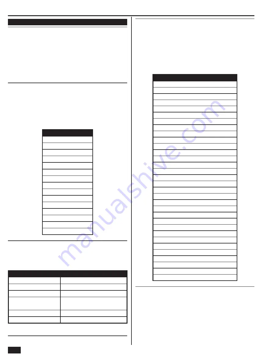
SENSOR TYPES

(00) unused

(01) exit/entry 1

(02) exit/entry 2

(03) perimeter

(04) interior follower

(05) day zone

(06) 24-hour silent alarm

(07) 24-hour audible alarm

(08) 24-hour auxiliary alarm

(09) 24-hour fi re

(10) interior with delay

(14) 24-hour carbon monoxide

(16) 24-hour fi re with verifi cation

(23) no response type

(24) silent burglary

 Select RF sensor (#) equipment type
DEFAULT: Varies by RF sensor type


NOTE: This question is only displayed when certain sensor types are selected. 
The equipment type selection will affect the sensor’s extended reporting code.

The following sensor types require equipment type selection:

SENSOR TYPE

EQUIPMENT TYPES AVAILA

B

LE

(04) interior follower

(1) = motion  (2) = contact

(06) 24-hour silent alarm

(1) = contact  (11) = emergency

(07) 24-hour audible alarm

(1) = contact  (11) = emergency

(08) 24-hour auxiliary alarm

(1) = contact  (6) = freeze  (8) = water

(10) = temperature  (11) = emergency

(10) interior with delay

(1) = motion  (2) = contact

(23) no response type

(1) = contact  (2) = motion

•  Select the equipment type that matches the sensor equipment using the 

 or 

 arrows, or enter the equipment type number directly on the keypad.

Select RF  sensor (#) equipment code
DEFAULT: (0000) other

The equipment code is a 4-digit code that is assigned to the model of sensor 
being used. The Control Panel will display a list of sensor models and their 
associated 4-digit equipment code.

•  Select the model of RF sensor being programmed for this 

sensor number using the 

 or 

 arrows, or enter the 

equipment code number directly on the keypad.

•  Select “(0000) other” if the sensor model is not shown on the list. The 

equipment code for the sensor can be entered using the next sub-question.

SENSOR EQUIPMENT CODES

(0000) other

(0862) DW10-345 thin door/window contact

(0863) DW20R-345 recessed door contact

(0869) PIR1-345 PIR with pet immunity

(0864) GB1-345 glass break detector

(0895) SMKT2-345 GE smoke/heat detector (USA/Canada)

(1058) SMKT3-345 2gig smoke detector

(0872) SMKE1-345 smoke detector (USA)

(0871) SMKE1-345C smoke detector (Canada)

(0868) PANIC1-345 panic button remote

(0860) CO1-345 CO detector (USA)

(0859) CO1-345C CO detector (Canada)

(1026) CO3-345 2gig CO detector (USA/Canada)

(0873) TAKE-345 takeover module

(0637) HW D/W “5816”

(0470) HW R-D/W “5818MNL”

(0533) HW PIR “5890”

(0530) HW PIR “5894PI”

(0519) HW Glass Break “5853”

(0589) HW Smoke “5808W3”

(0557) HW Heat Sensor “5809”

(0624) HW Flood Sensor “5821”

(0491) HW Panic Pendant “5802MN2”

(0655) Existing door/window contact

(0609) Existing motion detector

(0475) Existing glass break detector

(0616) Existing smoke detector

(0692) Existing CO detector

(0708) Existing heat sensor

(0556) Existing fl ood/temp sensor

(1061) GARAGE01 Resolution Products tilt sensor

(1063) DBELL1-345 2gig doorbell

Enter  RF sensor (#) other equipment code (0-9999)
DEFAULT: 0


NOTE: This question is only displayed if “(0000) other” 
is selected for a sensor’s equipment code.

The equipment code is a 4-digit code that is assigned to the model of sensor being 
used. If new equipment becomes available, the new equipment code should be 
entered here if the new equipment is not listed in the Sensor Equipment Codes 
table above.

•  Enter the equipment code number directly on the keypad for the 

RF sensor. (Enter “0” if the new equipment code is unknown.)

Содержание GO!control 2GIG-CNTRL2

Страница 1: ...Wireless Security System Installation Programming Instructions 2GIG CNTRL2 2GIG CP2...

Страница 2: ...e ceiling Do not install smoke alarms where normal ambient temperatures are above 100 F 37 8 C or below 40 F 4 C Also do not locate alarm in front of air conditioners heating registers or other locati...

Страница 3: ...ounder Disable Icon 14 Backup Battery Status Icon 14 Test Mode Icon 14 Touch Screen Keypad Traffic Icon 14 GSM Radio Icon 14 Interior Sensor Open Icon 14 Programming Navigation 15 Navigation Arrows Go...

Страница 4: ...requirements to qualify for a discount For an ETL smoke alarm system use only approved model smoke detectors with this Control Panel NOTE Some cities and municipalities may require an alarm system per...

Страница 5: ...subscribers can query and control their system using a computer browser from anywhere in the world The Alarm com server can also send messages time corrections and software updates to the Control Pan...

Страница 6: ...lashes ORANGE when ANY sensor is open not ready to arm Flashes RED while system is armed HOME BUTTON INDICATOR THIRD HAND HANGER STRAP Hooks onto mounting plate during installation to hold the Control...

Страница 7: ...ery connector into the connector on the Control Panel s circuit board 14 Swing the Control Panel up placing the bottom over the lip of the mounting bracket Push the top of the Control Panel into the m...

Страница 8: ...second button lockout Lithium battery 345 MHz ETL Listed 2GIG GB1 Glass Break Detector Monitors for the sound of breaking glass Two test LEDs Dual shatter recognition technology thud then crash Lithiu...

Страница 9: ...module Locking connector 2GIG ANT4X External In wall GSM Antenna Antenna installs in the wall behind Control Panel 2 foot cable Plugs into GSM module Locking connector 2GIG BATT1 Standard Battery Pac...

Страница 10: ...rmally open N O or normally closed N C End of line resistors EOLR can also be used to supervise the loops Only contacts should be used with the hardwired loops The Control Panel does not support power...

Страница 11: ...LCO INPUT DROP SIDE OFTHE BOX OR ANY EARTH GROUNDS 3 At the demarcation box connect the RED cable wire to the box RING and the GREEN cable wire to the box TIP 4 At the demarcation box connect the BLAC...

Страница 12: ...as simply plug the antenna connector into the GSM module The antenna will drop into the wall or mount in the attic with the cable passing through the slot in the Control Panel s mounting plate See Fig...

Страница 13: ...ug the backup battery pack s connector into the connector on the Control Panel s circuit board The Control Panel will not recognize that the battery is connected until AC power is connected to the pow...

Страница 14: ...e displayed To arm the system without an entry delay un check the ENTRY DELAY check box To arm silently without sounding the Exit Delay beeps check the SILENT EXIT check box Stay Mode arming always ha...

Страница 15: ...shortcut to help the installer access the Installer Toolbox quickly Pressing the lower right corner of the Home Screen while the system is disarmed will immediately display a code entry screen When t...

Страница 16: ...he system is being tested in Walk Test Mode the test mode icon will be displayed on the status bar Touch Screen KeypadTraffic Icon When the Control Panel is communicating to a touch screen keypad the...

Страница 17: ...utton advances to the next programming question section The arrows select the next or previous programming sub question The arrows choose values for the question or move the cursor left and right alon...

Страница 18: ...allation The volume setting DOES NOT affect the volume of alarm sounds 9 Press to view the second toolbox screen 10 Press BACKLIGHTTIMEOUT and set the display lighting timeout 11 Press SET DATE and SE...

Страница 19: ...delay restart 0 1 1 enabled Q QUESTION DEFAULT Q 28 Select quick exit 0 1 1 enabled Q 29 Enter periodic test in days 0 255 30 days Q 31 Enter cancel time in minutes 5 255 5 minutes Q 32 Select cancel...

Страница 20: ...ion trouble report but not an alarm when the system is disarmed 06 24 hour Silent Alarm This sensor type is active independent of the system arming status The code for silent panic is sent to the Cent...

Страница 21: ...LAUNDRY 127 LEFT 128 LEVEL 129 LIBRARY 130 LIGHT 131 LIGHTS 132 LIQUOR 133 LIVING 134 LOADING 135 LOCK 136 LOFT 137 LOW WORD 138 MAIN 139 MAINTENANCE 140 MASTER 141 MEDICAL 142 MEDICINE 143 MENU 144 M...

Страница 22: ...umber 01 48 Sensor Type Exit entry perimeter interior etc Sensor Equipment Type Certain sensor types will ask for equipment type Sensor Equipment Code Sensor model door window PIR smoke detector etc S...

Страница 23: ...ON KEYPAD OR PRESS TO SELECT FROM LIST OR ENTER ON KEYPAD OR PRESS TO SELECT FROM LIST OR ENTER ON KEYPAD OR PRESS TO SELECT FROM LIST OR ENTER ON KEYPAD OR PRESS TO SELECT FROM LIST OR insert PRESS...

Страница 24: ...arrows or enter the equipment type number directly on the keypad Select RF sensor equipment code DEFAULT 0000 other The equipment code is a 4 digit code that is assigned to the model of sensor being u...

Страница 25: ...button can be used to recall the last programmed sensor s serial number The sensor number will be filled in automatically if LEARN is used Select RF sensor dialer delay 0 1 DEFAULT Enabled 1 Required...

Страница 26: ...announcement and chime options for the sensor Wired Sensor Summary Screen After setting all the options for a sensor the wired sensor summary screen is displayed The screen can also be displayed for p...

Страница 27: ...ol Panel can be used with new or existing wired sensors If this wired sensor is new for the installation leave the default of new 0 If this wired sensor is already installed select existing 1 Select w...

Страница 28: ...button RF Key Fob Summary Screen After setting all the options for a sensor the key fob summary screen is displayed The screen can also be displayed for programmed key fobs during key fob program edit...

Страница 29: ...quipment age 0 1 DEFAULT New 0 The Control Panel can be used with new or existing key fobs If this fob is new for the installation leave the default of new 0 If this fob is already installed select ex...

Страница 30: ...een After setting all the options for a sensor the RF keypad summary screen is displayed The screen can also be displayed for programmed RF keypads during RF keypad program editing by pressing the SUM...

Страница 31: ...the Control Panel will learn the RF keypad s serial number TS1 WirelessTouch Screen Keypads For 2GIG TS1 Wireless Touch Screen Keypads press LEARN The Control Panel will display Pair with TS 1 Initia...

Страница 32: ...HIFT button accesses the pound and star symbols The P button adds a 3 second pause to the dialing NOTE If a second Central Station telephone number is programmed with question Q 41 the Control Panel w...

Страница 33: ...e supervised If the wiring to the sounder is cut for 15 30 or 45 seconds a bell trouble report can be sent to the Central Station The default 0 disables external sounder supervision To supervise the e...

Страница 34: ...information on setting the cancel report trigger time NOTE This default can be changed without affecting SIA CP 01 compliance Q 33 Select cross sensor 47 48 0 1 DEFAULT Disabled 0 The Control Panel c...

Страница 35: ...sses B C D E and F characters Q 42 Select remote control phone 0 3 DEFAULT Data and voice 3 This setting controls remote telephone access to the system The data option is for the installer It allows a...

Страница 36: ...trouble beeps from sounding from 10 pm to 9 am The trouble s will still be displayed and immediately reported to the Central Station and can be acknowledged but they won t sound beeps until after 9 a...

Страница 37: ...shutdown until the time of disarm and the sensor is closed The default 0 prevents alarm restore reports To allow alarm restore reports select enabled 1 Q 58 Select trouble restore reports to CS 0 1 DE...

Страница 38: ...light saving end week Q 71 Select system tamper causes trouble 0 1 DEFAULT Enabled 1 The Control Panel s case has a tamper switch that detects if the case has been opened The system can be programmed...

Страница 39: ...isible 1 The Z Wave home services feature can be enabled or disabled with various remote control access options The default 1 displays the SERVICES button but will show a message that the feature is c...

Страница 40: ...1 DEFAULT Disabled 0 This setting enhances system operation in personal emergency applications and also provides the dealer with the option of the siren sounding until the bell cut off or to the end...

Страница 41: ...permitted 4 Setup each User Code with the User Access Option Screen Each User Code can be set to be currently valid or not or to have conditional validity depending on a time and date schedule Refer...

Страница 42: ...ome active again To re enable the sounder manually follow these steps 1 From the Installer Toolbox Screen press ENABLE SOUNDER 2 A confirmation screen will be displayed Press OK Zone ReportingTest To...

Страница 43: ...est report to the Central Station Exiting the Walk Test Mode will send a stop test report to the Central Station To perform a walk test follow these steps 1 From the Installer Toolbox screen press WAL...

Страница 44: ...Installer Toolbox TelephoneTest The telephone test checks the land line connection to the Central Station through the Control Panel s built in digital communicator The test is accessed through the Us...

Страница 45: ...s Industry Canada Notices NOTICE The ringer equivalence number REN assigned to each terminal device provides an indication of the maximum number of terminals allowed to be connected to a telephone int...

Страница 46: ...exit delay restart 0 1 1 enabled Q QUESTION DEFAULT Q 28 Select quick exit 0 1 1 enabled Q 29 Enter periodic test in days 0 255 30 days Q 31 Enter cancel time in minutes 5 255 5 minutes Q 32 Select c...

Страница 47: ...126 LAUNDRY 127 LEFT 128 LEVEL 129 LIBRARY 130 LIGHT 131 LIGHTS 132 LIQUOR 133 LIVING 134 LOADING 135 LOCK 136 LOFT 137 LOW WORD 138 MAIN 139 MAINTENANCE 140 MASTER 141 MEDICAL 142 MEDICINE 143 MENU...

Страница 48: ...46 Notes...

Страница 49: ...47 Notes...

Страница 50: ...panel internal features 4 Control panel location 5 Control panel location height 5 Control panel mounting 11 Control panel mounting plate 8 Control panel wiring 11 Control panel wiring diagram 2 Cross...

Страница 51: ...31X telephone jack 9 S Saving programming 39 Security screen 12 Select keyfob remote arming mode on system not ready 38 Select siren mode 38 Sensor signal loss through materials 5 Sensor types 18 Sens...

Страница 52: ...v1 9 233497 E Copyright 2012...

Отзывы: