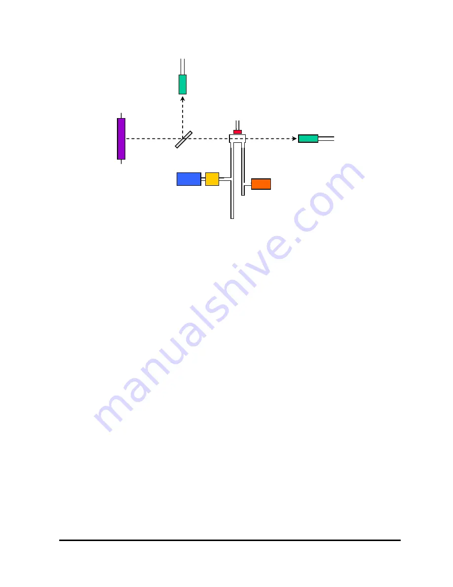
Model 106-H Ozone Monitor Manual Rev. D-2
2
When there is no ozone in the cell, a difference in light intensity at the reference and
sample photodiodes can be expected, and it will cause a zero offset in the readings.
This light intensity difference is inherent in the instrument due to the different
properties of the two photodiodes, drift in the angle of the beamsplitter, contamination
in the cell and thermal drift in any of the optical components. The zero drift has been
determined to be less than or equal to 2% of full scale per month, non-cumulative, and
can easily be corrected for by using the zero function described below. The zero drift
does not affect the slope calibration factor in any way, and the instrument does not
need to be recalibrated after performing the zeroing function.
The pressure and temperature within the absorption cell are measured so that the
ozone concentration can be expressed as a mixing ratio in percent by volume (vol%).
The fraction of the sample that is ozone can then be calculated and used to determine
the ozone concentration in percent by weight in either air (wt% air) or oxygen (wt%
O
2
), in g/m
3
, or in Ng/m
3
. The instrument displays and records the cell temperature
and pressure in addition to the ozone concentration. The cell pressure is displayed
and logged in units of mbar, torr, or psia and the cell temperature in units of either °C,
°F, or K.
1.2
Calibration and Zeroing Overview
In principle, the measurement of ozone by UV absorption requires only a zero
calibration to account for the different light intensities at the reference and sample
photodiodes. However, non-linearity of the photodiode response and electronics can
result in a small measurement error. Therefore, each instrument is compared with a
Sample
Photodiode
Hg Lamp
Absorption
Cell
Pressure Relief
and Scrubber
Temperature
Sensor
Sample Inlet
Reference
Photodiode
Beamsplitter
Pressure Sensor
Sample Outlet
Figure 1.1. Schematic Diagram of the Model 106-H Ozone Monitor.


