Chapter 3 Switch Hardware Overview
XS3900-48F User’s Guide
51
1
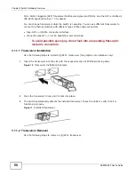
Open the transceiver’s latch (latch styles vary).
Figure 12
Opening the Transceiver’s Latch Example
2
Pull the transceiver out of the slot.
Figure 13
Transceiver Removal Example
3.2 Rear Panel
The following figures show the rear panel of the Switch. The rear panels contain:
• Two slots for fan modules (A)
• Two slots for power modules with power receptacles (B)
Figure 14
Rear Panel
3.2.1 Power Connection
Make sure you are using the correct power source and that no objects obstruct the airflow of the
fans in both fan and power modules.
The Switch uses two power supply modules, one of which is redundant, so if one power module fails
the system can operate on the remaining module. The power connections are on the front of each
power module.
Use the following procedure to connect the Switch to a power source after you have installed it in a
rack.
B
A
A
B
Summary of Contents for XS-3900-48F
Page 15: ...15 PART I User s Guide ...
Page 16: ...16 ...
Page 48: ...Chapter 2 Tutorials XS3900 48F User s Guide 48 ...
Page 62: ...Chapter 4 The Web Configurator XS3900 48F User s Guide 62 ...
Page 63: ...63 PART II Technical Reference ...
Page 64: ...64 ...
Page 227: ...Chapter 26 VLAN Mapping XS3900 48F User s Guide 227 ...
Page 320: ...Appendix A Common Services XS3900 48F User s Guide 320 ...
Page 332: ...Index XS3900 48F User s Guide 332 ...


