Chapter 3 Hardware Overview
GS-2750 User’s Guide
45
To connect the power to the Switch, insert the female end of power cord to the power
receptacle on the rear panel. Connect the other end of the supplied power cord to a power
outlet. Make sure that no objects obstruct the airflow of the fans.
The Switch’s AC unit requires a power supply of 100~240 VAC, 0.8 A.
3.2.2 External Backup Power Supply Connector
The Switch supports external backup power supply (BPS).
The Switch constantly monitors the status of the internal power supply. The backup power
supply automatically provides power to the Switch in the event of a power failure. Once the
Switch receives power from the backup power supply, it will not automatically switch back to
using the internal power supply even when the power is resumed.
3.2.3 Console Port
For local management, you can use a computer with terminal emulation software configured
to the following parameters:
• VT100 terminal emulation
• 9600 bps
• No parity, 8 data bits, 1 stop bit
• No flow control
Connect the male 9-pin end of the RS-232 console cable to the console port of the Switch.
Connect the female end to a serial port (COM1, COM2 or other COM port) of your computer.
3.3 LEDs
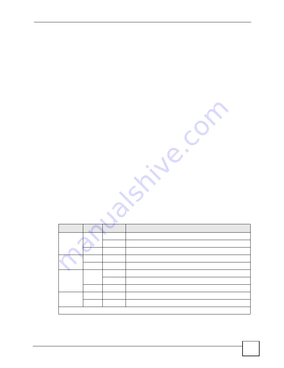
The following table describes the LEDs.
Table 3
LEDs
LED
COLOR STATUS
DESCRIPTION
BPS
Green
Blinking
The system is receiving power from the backup power supply.
On
The backup power supply is connected and active.
Off
The backup power supply is not ready or not active.
PWR
Green
On
The system is turned on.
Off
The system is off.
SYS
Green
Blinking
The system is rebooting and performing self-diagnostic tests.
On
The system is on and functioning properly.
Off
The power is off or the system is not ready/malfunctioning.
ALM
Red
On
There is a hardware failure.
Off
The system is functioning normally.
10/100/1000 Mbps RJ-45 Ethernet Ports
Summary of Contents for GS-2750
Page 2: ......
Page 7: ...Safety Warnings GS 2750 User s Guide 7 This product is recyclable Dispose of it properly ...
Page 8: ...Safety Warnings GS 2750 User s Guide 8 ...
Page 26: ...List of Figures GS 2750 User s Guide 26 ...
Page 32: ...32 ...
Page 40: ...Chapter 2 Hardware Installation and Connection GS 2750 User s Guide 40 ...
Page 48: ...48 ...
Page 58: ...Chapter 4 The Web Configurator GS 2750 User s Guide 58 ...
Page 64: ...Chapter 5 Initial Setup Example GS 2750 User s Guide 64 ...
Page 70: ...Chapter 6 System Status and Port Statistics GS 2750 User s Guide 70 ...
Page 82: ...Chapter 7 Basic Setting GS 2750 User s Guide 82 ...
Page 84: ...84 ...
Page 120: ...Chapter 11 Spanning Tree Protocol GS 2750 User s Guide 120 ...
Page 134: ...Chapter 15 Link Aggregation GS 2750 User s Guide 134 ...
Page 144: ...Chapter 17 Port Security GS 2750 User s Guide 144 ...
Page 155: ...Chapter 19 Policy Rule GS 2750 User s Guide 155 Figure 73 Policy Example example ...
Page 156: ...Chapter 19 Policy Rule GS 2750 User s Guide 156 ...
Page 160: ...Chapter 20 Queuing Method GS 2750 User s Guide 160 ...
Page 166: ...Chapter 21 VLAN Stacking GS 2750 User s Guide 166 ...
Page 194: ...Chapter 23 Authentication Accounting GS 2750 User s Guide 194 ...
Page 220: ...220 ...
Page 232: ...Chapter 28 Differentiated Services GS 2750 User s Guide 232 ...
Page 242: ...Chapter 29 DHCP GS 2750 User s Guide 242 ...
Page 252: ...Chapter 30 VRRP GS 2750 User s Guide 252 ...
Page 254: ...254 ...
Page 278: ...Chapter 32 Access Control GS 2750 User s Guide 278 ...
Page 280: ...Chapter 33 Diagnostic GS 2750 User s Guide 280 ...
Page 284: ...Chapter 34 Syslog GS 2750 User s Guide 284 ...
Page 298: ...Chapter 39 Routing Table GS 2750 User s Guide 298 ...
Page 301: ...301 PART VI Product Specifications Product Specifications 303 ...
Page 302: ...302 ...
Page 310: ...310 ...
Page 322: ...Appendix B Legal Information GS 2750 User s Guide 322 ...
Page 328: ...Appendix C Customer Support GS 2750 User s Guide 328 ...


