Chapter 30 VRRP
GS-2750 User’s Guide
244
If switch
A
(the master router) is unavailable, switch
B
takes over. Traffic is then processed by
switch
B
.
30.2 VRRP Status
Click
IP Application
>
VRRP
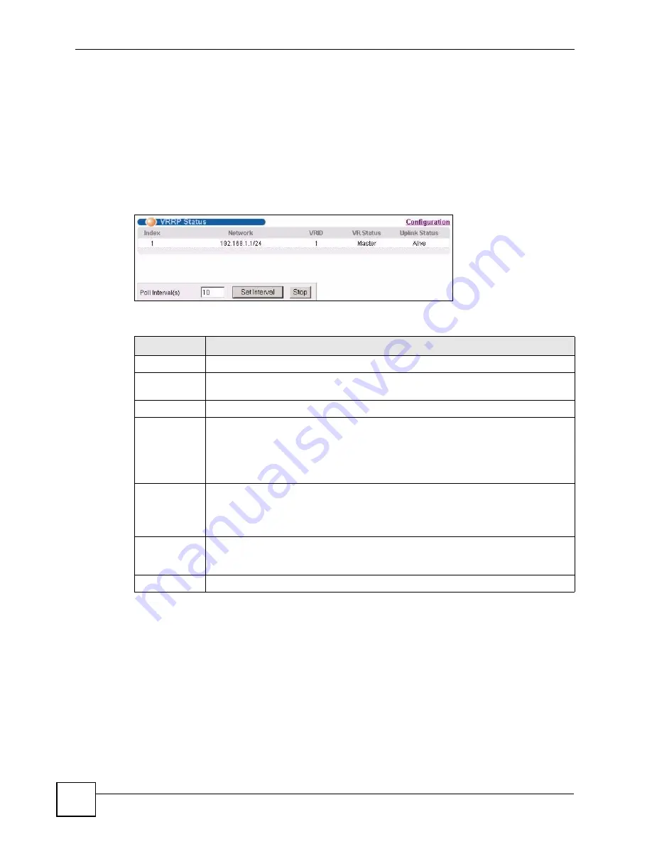
in the navigation panel to display the
VRRP Status
screen as
shown next.
Figure 131
IP Application > VRRP Status
The following table describes the labels in this screen.
30.3 VRRP Configuration
The following sections describe the different parts of the VRRP Configuration screen.
30.3.1 IP Interface Setup
Before configuring VRRP, first create an IP interface (or routing domain) in the
IP Setup
screen (see the
Section 7.6 on page 78
for more information).
Table 93
IP Application > VRRP Status
LABEL
DESCRIPTION
Index
This field displays the index number of a rule.
Network
This field displays the IP address and the subnet mask bits of an IP routing domain
that is associated to a virtual router.
VRID
This field displays the ID number of the virtual router.
VR Status
This field displays the status of the virtual router.
This field is
Master
indicating that this Switch functions as the master router.
This field is
Backup
indicating that this Switch functions as a backup router.
This field displays
Init
when this Switch is initiating the VRRP protocol or when the
Uplink Status
field displays
Dead
.
Uplink Status
This field displays the status of the link between this Switch and the uplink gateway.
This field is
Alive
indicating that the link between this Switch and the uplink gateway
is up. Otherwise, this field is
Dead
.
This field displays
Probe
when this Switch is check for the link state.
Poll Interval(s) The text box displays how often (in seconds) this screen refreshes. You may change
the refresh interval by typing a new number in the text box and then clicking
Set
Interval
.
Stop
Click
Stop
to halt system statistic polling.
Summary of Contents for GS-2750
Page 2: ......
Page 7: ...Safety Warnings GS 2750 User s Guide 7 This product is recyclable Dispose of it properly ...
Page 8: ...Safety Warnings GS 2750 User s Guide 8 ...
Page 26: ...List of Figures GS 2750 User s Guide 26 ...
Page 32: ...32 ...
Page 40: ...Chapter 2 Hardware Installation and Connection GS 2750 User s Guide 40 ...
Page 48: ...48 ...
Page 58: ...Chapter 4 The Web Configurator GS 2750 User s Guide 58 ...
Page 64: ...Chapter 5 Initial Setup Example GS 2750 User s Guide 64 ...
Page 70: ...Chapter 6 System Status and Port Statistics GS 2750 User s Guide 70 ...
Page 82: ...Chapter 7 Basic Setting GS 2750 User s Guide 82 ...
Page 84: ...84 ...
Page 120: ...Chapter 11 Spanning Tree Protocol GS 2750 User s Guide 120 ...
Page 134: ...Chapter 15 Link Aggregation GS 2750 User s Guide 134 ...
Page 144: ...Chapter 17 Port Security GS 2750 User s Guide 144 ...
Page 155: ...Chapter 19 Policy Rule GS 2750 User s Guide 155 Figure 73 Policy Example example ...
Page 156: ...Chapter 19 Policy Rule GS 2750 User s Guide 156 ...
Page 160: ...Chapter 20 Queuing Method GS 2750 User s Guide 160 ...
Page 166: ...Chapter 21 VLAN Stacking GS 2750 User s Guide 166 ...
Page 194: ...Chapter 23 Authentication Accounting GS 2750 User s Guide 194 ...
Page 220: ...220 ...
Page 232: ...Chapter 28 Differentiated Services GS 2750 User s Guide 232 ...
Page 242: ...Chapter 29 DHCP GS 2750 User s Guide 242 ...
Page 252: ...Chapter 30 VRRP GS 2750 User s Guide 252 ...
Page 254: ...254 ...
Page 278: ...Chapter 32 Access Control GS 2750 User s Guide 278 ...
Page 280: ...Chapter 33 Diagnostic GS 2750 User s Guide 280 ...
Page 284: ...Chapter 34 Syslog GS 2750 User s Guide 284 ...
Page 298: ...Chapter 39 Routing Table GS 2750 User s Guide 298 ...
Page 301: ...301 PART VI Product Specifications Product Specifications 303 ...
Page 302: ...302 ...
Page 310: ...310 ...
Page 322: ...Appendix B Legal Information GS 2750 User s Guide 322 ...
Page 328: ...Appendix C Customer Support GS 2750 User s Guide 328 ...


