background image

GDP-32

24 

INSTRUCTION MANUAL


September 2015 

Section 4, Page 24 

GDP-32

24


<0418d_GDPNET_NetConnect> 

MAP NETWORK DRIVE 

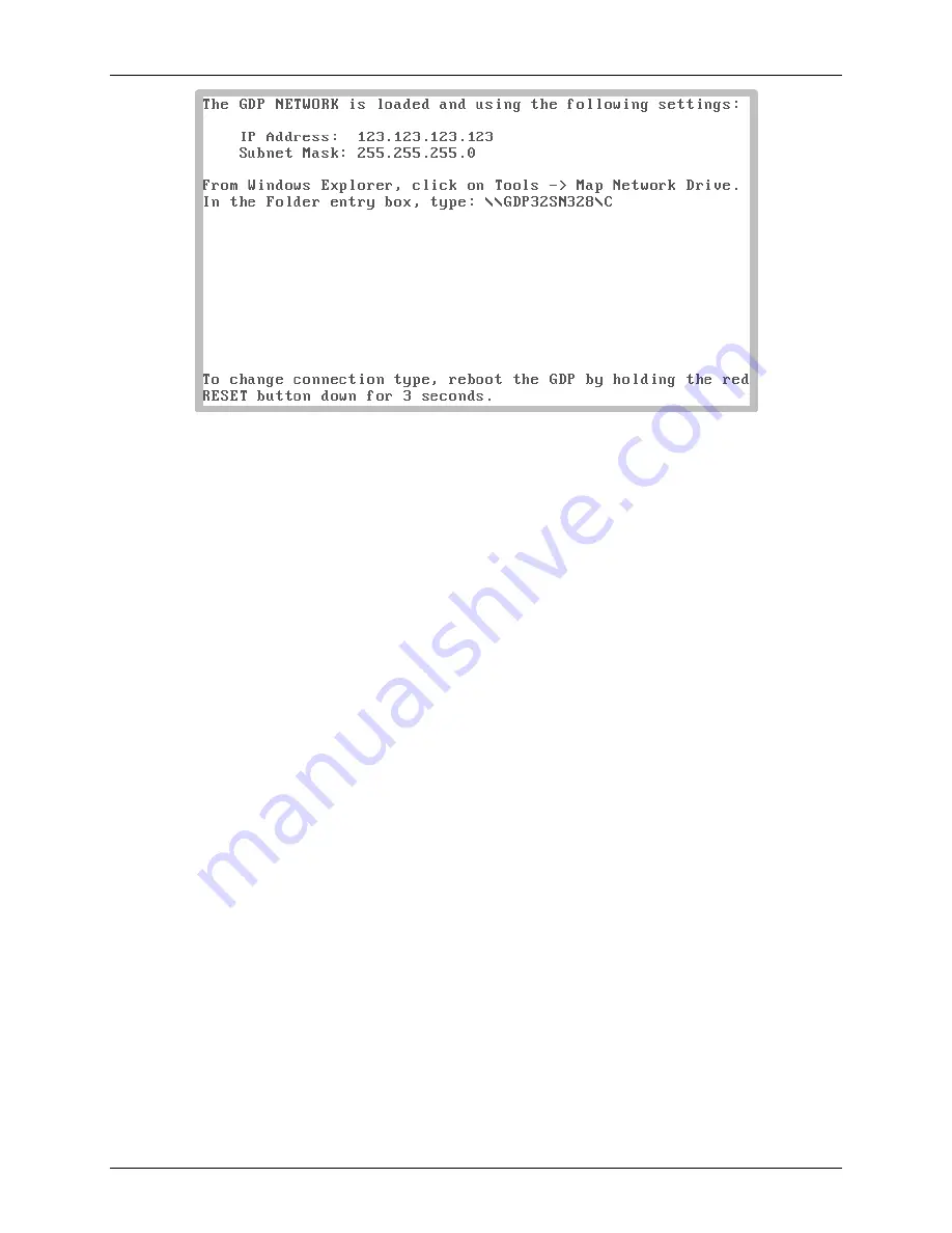
After  connecting  either directly  or  through  the network,  the  GDP  drive  should  be  mapped  as  a 
drive  to  the PC  or  laptop  computer.    Depending  on  the  version  of  Windows  or  other  operating 
system, the specific method of mapping a drive may differ.  From Windows Explorer, click on 

Tools->Map Network Drive

, or browse to Computer, then click on 

Map network 

drive

 in the tool bar.  Enter the network name as displayed on the connect screen of the GDP, 

into  the  Folder  field  of  the  dialog  box.    The  name  will  be  something  like 

\\GDP32SNxxx\C

”  where “

xxx

” will be the front panel serial number of the GDP.  Click 

on

 Finish 

to map the drive.   

WARNING:    Never  set  GDP  file  or  folder  attributes  and  properties  from  the  PC  or  laptop 
computer’s 

File Explorer

.  This can make the GDP system unstable.  File attributes on the GDP 

must NEVER be set to “

Read Only

” or “

Hidden

”.   

FILE TRANSFER 

Files can now be transferred to or from the GDP using either Windows Explorer, Copy/Paste or 
Drag-n-drop methods.  Some utilities such as TerraCopy can also be used.   

The current data cache files for all programs are found in the root directory of the receiver's flash 
drive, and follow the same naming convention.  Each program has its own data cache file.  The 
name  is  prefixed  with  the  digits  “24”,  followed  by  the  name  of  the  program,  and  have  the 
extension  “CAC”.    The  CSAMT  program  cache  for  example,  is  named  “24CSAMT.CAC”.  
When cache files are archived, they are moved to the \DATA folder, and can be given any name, 
but will always have the extension “CAC”.   

There  are  two  board  calibrate  files  on  the  GDP.    They  are  both  located  in  the  root  directory.  
They are 24BOARD.CAL and 24BRDAMT.CAL.   


Summary of Contents for GDP-32

Page 1: ...ANUAL SYNCHRONIZATION 10 4 8 SET TIME 11 4 9 SYNC CHK 13 4 10 FIELD SURVEY PROGRAM 14 4 11 JOB_INFO SCREEN 15 4 12 LINE SETUP 16 4 13 ACQUISITION CONFIGURATION 17 4 14 CHANNEL TABLE 18 4 15 CHECK FIEL...

Page 2: ...ck Field connections Acquire Data Check Data 6 Transfer Data Simple menus make operating the GDP 3224 straightforward The easiest way to become familiar with the receiver operation is to try the vario...

Page 3: ...r 2015 CURSOR POSITION To position the cursor on the LCD display use the Cursor Control Keys or and To cycle through available options labels and numbers use the Rotary Entry Keys and Pg Dn NEXT FIELD...

Page 4: ...ith an XMT transmitter controller both the receiver and XMT should be powered on for at least an hour before syncing and acquiring data Press the button located on the Front Panel The unit beeps and t...

Page 5: ...sure all the channels to be calibrated are turned on 3 Set the frequency to the lowest frequency that will be used during the survey 4 Select the notch filter to be used for the survey Note It is good...

Page 6: ...ecially as the environment changes will provide the best results Refer to Section 6 Setup and the sections for specific programs for more information about calibration and when to use METHOD 1SHOTCAL...

Page 7: ...closely to confirm and identify and real problem See the System Check section of this manual for more information FREQ Set to the lowest frequency to be used for the job CYCLES At least 2 cycles for t...

Page 8: ...GDP 3224 INSTRUCTION MANUAL September 2015 Section 4 Page 8 GDP 3224 0404a_24SYSCHK_Quick For more detailed instructions see Section 8 System Check...

Page 9: ...zation the receiver should be connected to either a GPS antenna or to an XMT transmitter See Section 6 Receiver Setup for more information about making the connections to a transmitter controller 0405...

Page 10: ...the receiver and XMT should be powered on for at least an hour before running SYNC If a fast beep sounds while pressing any of the crystal adjust keys no more adjustment is available on that particul...

Page 11: ...the and keys to make adjustments After making adjustments move the cursor back to the MODE field and make sure the GPS Local Time appears correct If not adjust the Local Time Differential setting When...

Page 12: ...GDP 3224 INSTRUCTION MANUAL September 2015 Section 4 Page 12 GDP 3224 0408b_24SYNC_TimeManl...

Page 13: ...the internal reference Set channel 2 comp field to XMT and connect the channel inputs to the XMT Sync Out ports Turn Off all other channels not connected to a synchronized signal Press 0409a_24SNCCHK...

Page 14: ...eters can be entered directly on the Main Menu screen Various submenu screens are accessed directly from the Main menu for entering more specific job or special setup parameters Functions such as Cali...

Page 15: ...job information submenu where Operator Transmitter and other job based data are entered Programs such as TEM also use this screen to enter loop antenna configurations delay times and other data which...

Page 16: ...all programs contain all the fields listed below some programs contain additional fields but all the fields in this portion of the screen should be inspected and modified if necessary TIME SERIES Set...

Page 17: ...if necessary FREQ Select the frequency to analyze CYCL Set the number of cycles to average STACKS Set the number of repetitions of data acquisition to perform Each stack will be recorded as its own b...

Page 18: ...l parameters Some examples are Note Refer to the appropriate Survey Program chapters for more information on setting up channels Any designator other than OFF will turn on channels for all programs wi...

Page 19: ...ELD CONNECTIONS The Channel Table is also used to verify electrode and coil field connections prior to data acquisition Pressing starts the Contact Resistance CRES function to measure the resistance o...

Page 20: ...to evaluate the process When data has been acquired the final results will be calculated and displayed When taking a single stack of data the GDP will display the message Press ESCAPE to discard CONT...

Page 21: ...mode Each program has its own cache viewing features and procedures Refer to the appropriate field survey manual for more information Press the function key to return to Data Acquisition mode 0417a_2...

Page 22: ...screen press to start the connection 0418a_GDPNET_ManualStart Enter an IP address consistent with the address of the PC or laptop The first 3 octets for the receiver address should be set to match tho...

Page 23: ...er to the Local Area Network hub with a standard cable From the Zonge Logo screen press to start the connection Press to select the AUTOMATIC settings 0418c_GDPNET_NetStart Press to initiate the conne...

Page 24: ...attributes and properties from the PC or laptop computer s File Explorer This can make the GDP system unstable File attributes on the GDP must NEVER be set to Read Only or Hidden FILE TRANSFER Files c...

Reviews: