ZMC432N Motion Controller User Manual V1.5
devices are connected into a loop, and disconnection is not allowed in the middle.
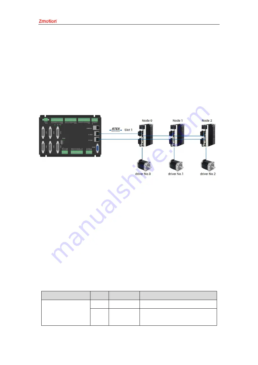
When connecting multiple RTEX drives, the TX port of the controller is connected to
the RX port of the first servo drive, and the TX port of the first servo drive is connected to
the RX port of the second drive, and so on, and the TX port of the last drive is connected
to the RX port of the controller to form a complete communication loop.
Device numbers and drive numbers are automatically numbered starting from 0 in
connection order, the same as the EtherCAT bus numbering convention.
See the configuration diagram below for the wiring method of RTEX:
3.10.
AXIS Differential Pulse Axis Interface
This product provides 6 local differential pulse axis interfaces, each interface is a
standard DB26 female socket. Each terminal provides 0V and +5V output, which can
provide 5V power for the encoder.
Before the axis is used, use ATYPE instruction to configure the axis type.
Controller has 6 pulses and 6 encoders, front 6 axes can select pulses or RTEX. Axis
6/7/8/9/10/11 can be configured as encoder, then are mapped into encoder of axis 0-5.
→
Interface Definition
Interface
Pin
Signal
Description
1
EGND
Negative pole of IO 24V power
2
IN24-
29/ALM
General input (recommended as
driver alarm)
Summary of Contents for ZMC432N
Page 1: ......


