background image


I/O Port 

Description 

USB 

Connect devices with USB connectors. There are 6 external USB ports available, 

(4 locate on the bottom and 2 left side ports).   

Mouse 

PS/2 mouse connector 

KB 

PS/2 keyboard connector 

PWR IN 

A 4 din rounded-power-jack for connecting an AC to DC +12V power adapter. 

PWR COM 

COM 1/2 support power RI/5/12V,   

refer to PWR COM Jumper Setting (as shown in the image below). 

Extend KB 

8-pin pitch 2.0 for keyboard. 

AUDIO OUT 

Earphone or speaker connector with 2 internal speakers. 

MIC IN 

Microphone connector 

DC12V OUT 

12VDC jack for customer display or 2

nd

 VGA monitor. 

Serial Ports 

There are 6 x COM ports available. 

3 x External COM :   

2 x COM with 5/12VDC Power Selectable    on pin-9 by jumper,   

1 x COM does not supply power. 

3 x Internal COM:   

1 x COM for Touch Option, 1x COM for MSR, 1 x COM Reserved. 

CASH DRAWER 

1 x RJ11 connector with selected 12/24V,   

* Please refer to PWR COM Jumper Setting (as shown in the image below). 

LAN 

1 x RJ-45 connector with link/act integrates speed LED and supports   

wake-from-LAN function. 

CF 

1 x CF card. 

VGA 

1 x 15 pin D-type connector serves to transmit VGA data to the monitor. 


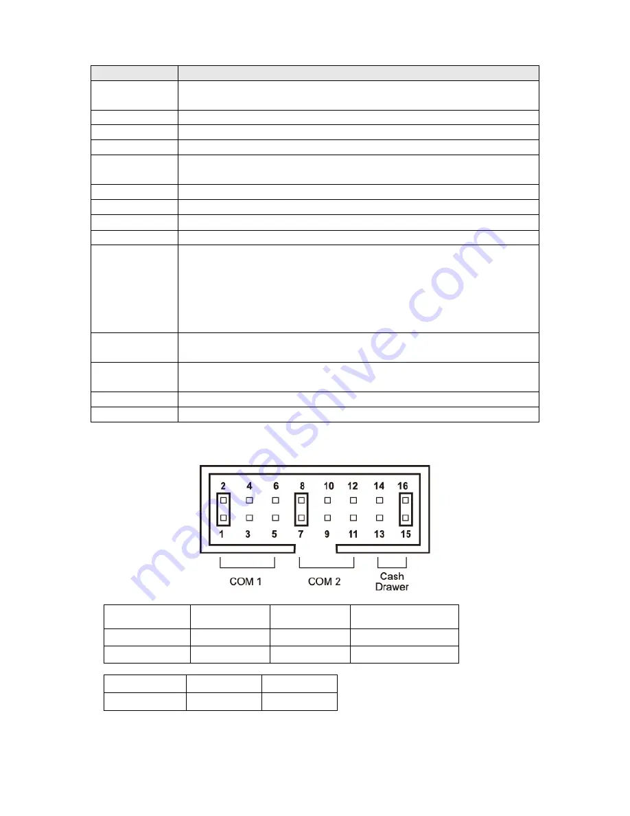
PWR COM and Cash Drawer Voltage Jumper Settings 


Setting 

+12V 

+5V 

Modem Ring In 

(Default) 

COM 1 

1-2 

3-4 

5-6 

COM 2 

7-8 

9-10 

11-12 


Setting 

+12V 

+24V 

Cash Drawer 

13-14 

15-16 


Summary of Contents for POP-950-D5

Page 1: ...Zircon Series All in One POS System User Manual POP 950 D5 Ver 1 2 Copyright Fametech Inc TYSSO 2013 ...

Page 2: ...PARTICULAR THE VENDOR SHALL NOT HAVE LIABILITY FOR ANY HARDWARE SOFTWARE OR DATA STORED OR USED WITH THE PRODUCT INCLUDING THE COSTS OF REPAIRING REPLACING OR RECOVERING SUCH HARDWARE SOFTWARE OR DATA WARNING The terminal has been tested and found to comply with the limits for a Class a digital device pursuant to Part 15 of the FCC rules These limits are designed to provide reasonable protection a...

Page 3: ...ire WARRANTY LIMITS If the product and the parts are disassembled by any person other than the authorized technicians the warranty will be terminated The users should consult his her dealer for any technical problems Warranty does not cover any damage caused by improper use TRADE MARKS AND SERVICE MARKS TYSSO is a registered trademark of FAMETECH INC Other brand and product names are trademarks an...

Page 4: ... with a third grounding pin This is a safety feature If your outlet does not accommodate the three wire plug have an electrician install a correct outlet or use an adapter to ground the appliance safely Do not leave out the safety purpose of the grounded plug Do not allow anything to rest on the power cord Do not locate the system where people may walk on the cord Do not make the power outlet and ...

Page 5: ...ceipt Printer Optional 15 2 6 1 Install Replace the Paper Roll 15 2 6 2 Buttons Indicators of Receipt Printer Unit 16 2 6 3 Dip Switch Configuration of the Receipt Printer 17 2 6 4 Virtual Serial Port Installation for USB Connection Only 19 2 6 5 Install the Driver and Setup of Receipt Printer Unit 24 2 7 Adjust the Customer Display Optional 30 2 8 Configuration of Customer Display 30 3 BIOS Setup...

Page 6: ...l the Graphics Driver 59 4 3 Install the Audio Driver 63 4 4 Install the LAN Driver 65 5 Install the Touch Screen Driver 67 5 1 Install the Driver of Resistive Type Touch Panel 68 5 2 Touch Screen Calibration Resistive Type 72 6 Peripherals Testing 75 6 1 Install the Wi Fi Driver Optional 76 6 2 Test Your Magnetic Stripe Card Reader MSR and i Button Module 80 6 3 Test Your Customer Display 86 6 4 ...

Page 7: ...ter Hidden under Base AC Power Cord Driver Utility CD Optional Accessories Magnetic Stripe Card Reader MSR Customer Display Wi Fi module Thermal Receipt Unit I Button Secondary Display For more information relating to the other optional peripherals please contact the local representatives or technical support personnel of the providers POS System AC Power Cord Driver Utility CD ...

Page 8: ...allel Port USB 6 x USB 2 0 External 2 x USB 2 0 Internal 1 reserved for touch screen Mini PCIe 1 x Internal PS 2 Mouse 1 x 6 pin Mini DIN PS 2 Key Board 1 x 6 pin Mini DIN LAN 1 x RJ 45 Giga LAN Support VGA 1 x DB 15 Female DC Out 1 x 12VDC Jack for Customer Display or 2nd Display Cash Drawer 1 x RJ 11 12 24 VDC Selectable Audio Jack 1 x Line Out 1 x MIC In 2 x Internal Speaker 2W Others Power Inp...

Page 9: ...Font B Effective Print Width 72mm Paper Width 79 5mm 0 5mm Paper Roll Diameter 83mm Paper Thickness 0 06 0 08mm Print Command ESC POS commands set compatible Auto Cutter Partial Paper End Detection Yes Over Heat Halt on Protection Yes Interface Printer Serial Multi I O Interface Serial Ethernet USB USB Ethernet Cash Drawer DC 24V 1A 6 Wire RJ 11 Socket Others Power Input Printer 24VDC 2 5A with Ex...

Page 10: ...18 x 87 x 45 mm Support Pole Telescopic Pole 280 459 mm adjustable Base 140 x 18 x 86 mm Horizontal Rotation 180 degree Tilting Angle 53 degree 4 step adjustable Operating Temperature 0 C 40 C Storage Temperature 10 C 50 C Relative Humidity 0 90 RH non condensing Optional Peripherals MSR 3 Track PS 2 or USB or COM i Button Dallas Key RS232 I F 2nd Display 8 4 10 4 12 1 15 with or without Touch Wi ...

Page 11: ...5 Dimensions Left View Front View Right View VFD Pole max height Right View VFD Pole min height ...

Page 12: ...Front View Rear View Touch Screen Power Switch Power Switch of Customer Display Receipt Slot Bottom I O Cover Customer Display Power Switch of Receipt Printer Unit Printer Cover Button Printer Cover Paper Feed Button HDD Cover ...

Page 13: ...7 Bottom View Side View Bottom I O Cover AC Power Cord Connector Left View Right View i Button MSR Side PS 2 USB Ports I O Ports for Printer Unit ...

Page 14: ...om I O Ports Side I O Ports I O Ports for Printer Unit Printer Unit is an optional part and may not include in the product Bottom I O Cover Bottom I O ports Side I O ports Printer I O ports USB Serial Port RJ 45 RJ 11 PWR ...

Page 15: ...k for customer display or 2nd VGA monitor Serial Ports There are 6 x COM ports available 3 x External COM 2 x COM with 5 12VDC Power Selectable on pin 9 by jumper 1 x COM does not supply power 3 x Internal COM 1 x COM for Touch Option 1x COM for MSR 1 x COM Reserved CASH DRAWER 1 x RJ11 connector with selected 12 24V Please refer to PWR COM Jumper Setting as shown in the image below LAN 1 x RJ 45 ...

Page 16: ... there s any physical damage or missing parts please contact your supplier immediately Please keep all packing materials in case you need to ship back the device for service Unpacking The product and accessories are packed in a paperboard carton And it is wrapped by foam padding for protection during shipping ...

Page 17: ...4 Plug the AC power cord to the power source for example electrical outlet 5 Turn on the switch of the Printer Unit and Customer Display if pre installed and the other optional peripherals 6 Turn on the POS System Note Always install the POS system and the optional peripherals on a flat clean and stable location surface with additional cushioned material for example blanket To prevent obstruction ...

Page 18: ...aterial for example blanket b Pull the HDD Module to the left to detach it from the POS unit Disconnect the HDD Cable to remove the HDD Module Remove the HDD Module c Loosen the securing screws to remove the hard disk from the bracket Then replace a new hard disk with protective film attached to the HDD d Re install the HDD module and replace the HDD cover to the POS HDD Cover HDD Slot With HDD Mo...

Page 19: ...here is a power connector in the bottom as image below illustrated Note To prevent injuries to the LCD Panel Carefully lay the front of the unit face down on a flat clean and stable surface with additional cushioned material for example blanket b Plug the AC power cord into the power connector c Plug the AC power cord in to the AC outlet ...

Page 20: ...ystem a Pull the Bottom I O cover and connect the optional peripherals to the POS system b Connect the PS 2 keyboard and mouse to the Side I O Ports c Arrange the cables as the peripherals are installed Push the Bottom I O Cover and set the POS system into place Note The Optional Accessory may not include in the package Please contact your local representative for further information Side I O port...

Page 21: ...ugh the printer slot Warning Do not pull out the paper with force through the slot If the paper does not feed easily check whether you are using the paper slot and there are no obstructions in the paper path a Press the button to open the printer cover b Place the receipt paper roll into the slot Align the paper roll to the left of the slot c Close the cover by pressing the cover Make sure the cov...

Page 22: ...r Printer Error Out of paper Printer head over heat or paper cutter error Paper Out of paper The Error Indicator is lit as well Self Test This function allows user to perform self test and print out the settings of the printer unit 1 Turn off the printer 2 Press and hold the Paper Feed Button 3 Turn on the Power Switch of the printer 4 Release the Paper Feed Button The Indicators would blink and t...

Page 23: ...pswitches of Receipt Printer bottom a Switch off the power and carefully lift up the POS system b Disconnect the cables from the I O ports of the printer unit c Loose the securing screw on the bottom left of the POS system as image below illustrated d Pull up to unhook the printer unit and then pull to detach the printer e Turn over the printer unit and open the cover of DIP Switch Cover in the bo...

Page 24: ...s 2 Audio Alarm Yes No 3 Print Density Dark Light 4 Two byte Character Code No Yes 5 Character Per Line 42 48 6 Cutter with Cash Drawer Yes No 7 8 Baud Rate Setting OFF The mark indicates the default value of each setting Baud Rate Setting DIP 7 DIP 8 19200 Default 9600 115200 38400 ...

Page 25: ...computer and the system will found a new hardware automatically and then initiate the Found New Hardware Wizard automatically as image below illustrated a Found New Hardware Wizard is initiated click Install from a specific location Advanced and then click Next to continue Printer Cable USB Cash Drawer Power Adaptor USB RS 232 RJ 45 RJ 11 PWR ...

Page 26: ...specify the location of driver click include this location in the search and Browse the specified folder manually c Browse the subfolder Virtual COM Driver x86 for Windows XP 32 bit version Click OK to continue ...

Page 27: ...21 d As the location of the driver is specified Click Next to continue e Start Notification Click Continue Anyway to continue ...

Page 28: ...e wizard is installing the driver g The driver of Virtual Serial Port is successfully installed Click Finish to exit Note Reboot the HOST PC It s recommended to reboot the HOST PC and proceed to the next step ...

Page 29: ...omatically when the printer is switched on You can Access My Computer Proprieties Hardware Device Manager Ports COM LPT and see the Virtual COM Port Number When turn on the printer the Virtual COM activates automatically Virtual Serial Port ...

Page 30: ...he CD and double click the folder Driver Utility to access the folder There are categorized folders for POS Terminal Peripherals and Touch Screen drivers Select Peripherals to access the subfolders To install the drivers of the Printer unit i Double click the folder Printer and access the subfolders j Select Printer Driver ...

Page 31: ...he PRPDRVEN EXE and follow the on screen instructions to install the driver l The setup wizard of receipt printer driver Click Next to continue m Select the appropriate operating system for your POS Click Next to continue ...

Page 32: ...26 n Module Type Setting Select the printer model number using the menu below o Default Printer Setting To set the printer as the default printer click the checkbox to confirm ...

Page 33: ...tting Select appropriate serial port COM 2 recommended or Virtual COM port according to your system setting Click Configure Port to continue q Configure Port Select the Bit per secnd Baud Rate to 19200 Click OK to continue ...

Page 34: ...28 r Click Install to Start Installation s Configuration Completed Click Finish to exit the menu Note Reboot the HOST PC It s recommended to reboot the HOST PC and proceed to the next step ...

Page 35: ...ur printer Start Printers and Faxes and double click the icon to enter Make sure the port of printer is correctly configured Access sub menu Ports and click to select the correct port for your printer Click Configure Port to examine the COM port setting Click OK to exit ...

Page 36: ...just the Display to the proper View Angle The maximum tilt angle is 53 degree 4 steps adjustable and the rotate angle is 180 degree Note Do Not rotate the display over 180 degree Please rotate the display clockwise or counter clockwise 2 8 Configuration of Customer Display There is a configuration utility to setup your pre installed customer display refer to the configuration instruction manual fo...

Page 37: ...tem as the figure below illustrated Insert the installation CD for the Operating System b Power on or reboot the system board when screen appears message as Press DEL to enter SETUP Press DEL key to run BIOS SETUP Utility Note To set CD ROM as the first boot device please access the BIOS Setup press DEL when switch on the terminal Access the Advanced BIOS Features and select the USB CD ROM as the ...

Page 38: ...ge Control Load Fail Safe Defaults Load Optimized Defaults Set Supervisor Password Set User Password Save Exit Setup Exit Without Saving Esc Quit Select Item F10 Save Exit Setup Time Date Hard Disk Type Standard CMOS Features Advanced BIOS Features Advanced Chipset Features Integrated Peripherals Power Management Setup PnP PCI Configurations PC Health Status ...

Page 39: ... ESC Exit F1 General Help Menu Level Change the day month year and century F5 Previous Values F6 Fail Safe Defaults F7 Optimized Defaults Date mm dd yy Thu Aug 11 2011 Time hh mm ss 11 28 10 Date Set system date Time Set system time IDE Channel 0 Master Slave Press Enter for IDE device automatic detection IDE Channel 2 Master Slave Press Enter for IDE device automatic detection IDE Channel 3 Maste...

Page 40: ... Logo EPA Show Phoenix AwardBIOS CMOS Setup Utility Advanced BIOS Features F5 Previous Values F6 Fail Safe Defaults F7 Optimized Defaults Press Enter Press Enter Disabled Enabled Enabled Enabled CDROM Hard Disk USB FDD Enabled On Fast Disabled Setup 1 4 Non OS2 No Disabled X X CPU Feature Press Enter to select CPU parameter Hard Disk Boot Priority Press Enter to select Hard Disk boot device priori...

Page 41: ...MPS Multiprocessor Specification Version 1 4 to added extended configuration tables to improve support for multiple PCI bus configurations and improve future expandability It is also required for a secondary PCI bus to work without the need for a bridge Select Version 1 1 for older Operating Systems OS Select For DRAM 64M Select OS2 only if you are running older version of IBM OS 2 Operating Syste...

Page 42: ... F5 Previous Values F6 Fail Safe Defaults F7 Optimized Defaults On Chip Frame Buffer Size Select share system memory 1MB or 8MB DVMT Mode DVMT Dynamic Video Memory Technology allowing the system to dynamically allocate memory resources according to the demands of the system at any point in time that improve efficiency of the memory allocated to either system or graphics processor Total GFX Memory ...

Page 43: ...m Help Menu Level Move Enter Select PU PD Value F10 Save ESC Exit F1 General Help PCI Express Port 1 PCI Express Port 2 PCI Express Port 3 PCI Express Port 4 PCI Express Port 5 PCI Express Port 6 PCI E Compliancy Mode Phoenix AwardBIOS CMOS Setup Utility PCI Express Root Port Func AUTO AUTO AUTO AUTO AUTO AUTO v1 0a F5 Previous Values F6 Fail Safe Defaults F7 Optimized Defaults ...

Page 44: ...ESC Exit F1 General Help OnChip IDE Device Onboard Device Super IO Device SecondIO Device USB Device Setting Phoenix AwardBIOS CMOS Setup Utility Integrated Peripherals Press Enter Press Enter Press Enter Press Enter Press Enter F5 Previous Values F6 Fail Safe Defaults F7 Optimized Defaults ...

Page 45: ...er UDMA IDE Secondary Slave UDMA Phoenix AwardBIOS CMOS Setup Utility OnChip IDE Device If your IDE hard drive supports block mode select Enabled for automatic detection of the optimal number of block read writes per sector the drive can support F5 Previous Values F6 Fail Safe Defaults F7 Optimized Defaults Enabled Enabled IDE Enhanced Mode Enabled Auto Auto Auto Auto Enabled Auto Auto Auto Auto I...

Page 46: ...e IDE interface Select Disabled to deactivate this interface if you install a primary and or secondary add in IDE interface IDE Primary Master PIO IDE Primary Slave PIO Secondary Master PIO Secondary Slave PIO The four IDE PIO Programmed Input Output fields let you set a PIO mode 0 4 for each of the four IDE devices that the onboard IDE interface supports Modes 0 through 4 provide successively inc...

Page 47: ... ESC Exit F1 General Help Onboard Lan1 ADO Control Onboard Lan Boot ROM Phoenix AwardBIOS CMOS Setup Utility Onboard Device F5 Previous Values F6 Fail Safe Defaults F7 Optimized Defaults Onboard Lan1 Enable Disable onboard Lan1 Onboard Lan Boot ROM Decide whether to invoke the boot ROM of the onboard LAN chip ...

Page 48: ...lues F6 Fail Safe Defaults F7 Optimized Defaults 3F8 IRQ4 2F8 IRQ3 Normal Hi Lo Enabled Half IR Rx2Tx2 378 IRQ7 SPP EPP1 7 3 Disabled Onboard Serial Port 1 Select serial port 1 address Disabled 3F8 IRQ4 2F8 IRQ3 3E8 IRQ4 2E8 IRQ3 or Auto Onboard Serial Port 2 Select serial port 2 address Disabled 3F8 IRQ4 2F8 IRQ3 3E8 IRQ4 2E8 IRQ3 or Auto UART Mode Select Select UART Mode IrDA ASKIR or Normal Onb...

Page 49: ...ity Second IO Device Onboard Serial Port 3 Serial Port 3 Use IRQ Onboard Serial Port 4 Serial Port 4 Use IRQ Onboard Serial Port 5 Serial Port 5 Use IRQ Onboard Serial Port 6 Serial Port 6 Use IRQ F5 Previous Values F6 Fail Safe Defaults F7 Optimized Defaults Onboard Serial Port 3 4 5 6 Select serial port address Serial Port 3 4 5 6 Use IRQ Select serial port IRQ Support IRQ sharing mode ...

Page 50: ...S Setup Utility USB Device Setting Enable or Disable Universal Host Controller Interface for Universal Serial Bus USB 1 0 Controller USB 2 0 Controller USB Operation Mode USB Keyboard Function USB Mouse Function USB Storage Function USB Mass Storage Device Boot Setting Enabled Enabled High Speed Enabled Enabled Enabled F5 Previous Values F6 Fail Safe Defaults F7 Optimized Defaults ...

Page 51: ...oenix AwardBIOS CMOS Setup Utility Power Management Setup x x F5 Previous Values F6 Fail Safe Defaults F7 Optimized Defaults ACPI Function Select ACPI Advanced Configuration and Power Management Enabled Disabled ACPI Suspend Type Select S1 POS type Soft Off by PWR_BTTN Select power button function Instant off Press power button will power off instantly Wake UP by PCI card Select wake up by PCI dev...

Page 52: ...em Help Menu Level Move Enter Select PU PD Value F10 Save ESC Exit F1 General Help Wake up by Lan Phoenix AwardBIOS CMOS Setup Utility PCI Express PM Function Disabled F5 Previous Values F6 Fail Safe Defaults F7 Optimized Defaults Wake up by Lan Select wake up by LAN Enabled Disabled ...

Page 53: ...ct initial display by PCI or Onboard device Reset Configuration Data Select Enabled to reset Extended System Configuration Data ESCD when you exit BIOS setup utility if you have installed new add on card and the system reconfiguration has caused such a serious conflict that the OS cannot boot Resources Controlled By BIOS can automatically configure the entire boot and Plug and Play compatible devi...

Page 54: ...nix AwardBIOS CMOS Setup Utility PC Health Status F5 Previous Values F6 Fail Safe Defaults F7 Optimized Defaults Disabled Disabled 34 C 93 F 33 C 91 F 4115 RPM 0 RPM 1 16 V 11 72 V 1 05 V 1 54 V 5 15 V 3 37 V 3 15 V 3 37 V Disabled Disabled Shutdown Temperature If CPU temperature reaches the setting value will automatic shutdown system CPU Warning Temperature If CPU temperature reaches the setting...

Page 55: ...neral Help Auto Detect PCI Clk Spread Spectrum Phoenix AwardBIOS CMOS Setup Utility Frequency Voltage Control F5 Previous Values F6 Fail Safe Defaults F7 Optimized Defaults Enabled Disabled Auto Detect PCI Clk Select Auto Detect PCI Clk Enabled Disabled Spread Spectrum Select Spread Spectrum Enabled Disabled ...

Page 56: ...ithout Saving Phoenix AwardBIOS CMOS Setup Utility Esc Quit Select Item F10 Save Exit Setup Load Fail Safe Defaults Standard CMOS Features Advanced BIOS Features Advanced Chipset Features Integrated Peripherals Power Management Setup PnP PCI Configurations PC Health Status Load Fail Safe Defaults Y N N This item will set configuration for non optimized system operation ...

Page 57: ... Password Save Exit Setup Exit Without Saving Esc Quit Select Item F10 Save Exit Setup Standard CMOS Features Advanced BIOS Features Advanced Chipset Features Integrated Peripherals Power Management Setup PnP PCI Configurations PC Health Status Load Optimized Defaults Y N N Load Optimized Defaults This item will restore factory default setting for optimized system operation ...

Page 58: ...r Password Save Exit Setup Exit Without Saving Esc Quit Select Item F10 Save Exit Setup Standard CMOS Features Advanced BIOS Features Advanced Chipset Features Integrated Peripherals Power Management Setup PnP PCI Configurations PC Health Status Enter Password Change Set Disabled Password If set supervisor password it will request typing password to enter BIOS setup utility ...

Page 59: ... Setup Exit Without Saving Esc Quit Select Item F10 Save Exit Setup Standard CMOS Features Advanced BIOS Features Advanced Chipset Features Integrated Peripherals Power Management Setup PnP PCI Configurations PC Health Status Enter Password Change Set Disabled Password If set user password will request typing password to enter BIOS setup utility and does not allow modifying configuration ...

Page 60: ...t Select Item F10 Save Exit Setup Save Data to CMOS Standard CMOS Features Advanced BIOS Features Advanced Chipset Features Integrated Peripherals Power Management Setup PnP PCI Configurations PC Health Status SAVE to CMOS and EXIT Y N Y This item confirm save configuration or not before exit BIOS setup utility Press Y and Enter to save configuration then reboot system Press N and Enter will back ...

Page 61: ...it Select Item F10 Save Exit Setup Abandon all Data Standard CMOS Features Advanced BIOS Features Advanced Chipset Features Integrated Peripherals Power Management Setup PnP PCI Configurations PC Health Status Quit Without Saving Y N N This item confirm save configuration or not before quit BIOS setup utility Press Y and Enter will not save configuration then reboot system Press N and Enter will b...

Page 62: ...erals and Touch Screen drivers To install the drivers of POS terminal a Double click the folder POS Terminal Driver b There are subfolders as image below illustrated Please access the folder Atom D525 for the drivers required c Select the folder as the operating system required i e double click the folder Win XP for the Windows XP system or the folder Win 7 for Windows 7 d There are categorized fo...

Page 63: ...57 4 1 Install the Chipset Driver a Open double click the folder Chipset b Double click the icon to start installation c Click Next to proceed d Read the License Agreement and click Yes to continue ...

Page 64: ...58 e Click Next to continue the setting process f Select Next to continue the setting process g Select Yes and click Finish and then restart the system ...

Page 65: ...nstall the Graphics Driver a Open double click the folder Graphics b Access the sub folder and double click Setup EXE to start the setting process c Click Next to continue Click Cancel to abort the installation ...

Page 66: ...60 d Click Next to proceed e Declaration of License Agreement click Yes to agree and continue ...

Page 67: ...61 f Click Next to continue g Click Next to continue ...

Page 68: ...62 h The graphic card driver is successfully installed It s recommended to restart the system after the driver is installed Click Finish to restart the computer ...

Page 69: ... Install the Audio Driver a Open double click the folder Audio b Double click the icon to initiate the Install Shield Wizard The Install Shield Wizard will extract the contents and then start the installation ...

Page 70: ...lick Next to start installing the driver to the computer d The audio driver is successfully installed It s recommended to restart the system after the driver is installed Click Finish to restart the computer ...

Page 71: ...4 4 Install the LAN Driver a Open double click the folder LAN b Access to the subfolder Double click the file Setup EXE to start the installation c Click Next to start installing the driver to the computer ...

Page 72: ...66 d Click Install to continue the setting process e Click Finish to finish the installation ...

Page 73: ...There are categorized folders for POS Terminal Peripherals and Touch Screen drivers To install the drivers of Resistive Touch Panel a Double click the folder Touch Driver to access the subfolder b There are drivers of Resistive type and SAW type touch screen To install the driver for Resistive type select double click the folder Resistive Touch to start installation ...

Page 74: ... for installation for example select Windows for Windows XP operating system b Select the subfolder according to the operating system installed for example select Win 7 Vista XP 2K ME98 32bits for the Windows XP 32 bit version c Double click the file Setup EXE to start the installation d Click Next to start the installation ...

Page 75: ...tion folder and click Next to continue f COM port RS 232 driver installation If the touch screen is for RS 232 interface please click the checkbox Install RS232 driver additionally to install the driver Click Next to continue ...

Page 76: ...70 g Multi monitor driver installation Click the checkbox Install Multi monitor driver to install the driver h Click Install to start the installation ...

Page 77: ...71 i Installation completed Click Finish to exit j Initializing the touch tool program k Installation completed There is an icon on the screen for quick launch ...

Page 78: ...een Calibration Resistive Type There is a Utility Touch Tool for Touch Screen Calibration a Double click the icon to access the utility b User can perform 4 point calibration by selecting the function 4 pts calibration ...

Page 79: ...ibration points on the screen Tap the blinking mark to complete the first calibration point Proceed to the next mark and complete all calibration points d The calibration is completed tap the icon Save to save the setting ...

Page 80: ...oint Calibration There are advanced 9 point calibration and 25 point calibration for more accurate calibration demands Access Advance menu and select either 9 pts linearization or 25 pts linearization to calibrate your touch screen ...

Page 81: ... operational Note For more information relating to the other optional peripherals please contact the local representatives or technical support personnel of the nearest providers Please place the supplied CD into the CD ROM driver Browse the CD and double click the folder Driver Utility to access the folder There are categorized folders for POS Terminal Peripherals and Touch Screen drivers Select ...

Page 82: ...SB Type Wi Fi module Open the folder WUG2700 USB to find the appropriate driver For Mini PCIe Type Wi Fi module Open the folder RT2860 Mini PCIe to find the appropriate driver Please refer to the local representative for the hardware information before install the driver a Open the folder to find the appropriate driver b Access the subfolders and double click the icon to install the driver ...

Page 83: ...77 c Click Yes to accept the terms of License Agreement and continue d Select Install driver only and click Next to continue ...

Page 84: ...78 e Click Install to begin Installation f The Wi Fi driver is successfully installed Click Finish to complete and exit the Wizard ...

Page 85: ...79 Note To access the wireless network and initiate the connection please refer to the service provider for further information ...

Page 86: ...80 6 2 Test Your Magnetic Stripe Card Reader MSR and i Button Module For RS 232 Interface a Execute Start All Programs Accessories Communications Hyper Terminal b Enter a name and press OK ...

Page 87: ...d press OK d Port Setting MSR i Button Module If the POS unit is equipped with MSR i Button module set Bits per second to 9600 Data bits to 8 Parity to Even Stop bits to 1 and Flow control to Hardware Press OK to continue ...

Page 88: ...it is equipped with MSR module only set Bits per second to 9600 Data bits to 8 Parity to None Stop bits to 1 and Flow control to Xon Xoff Press OK to continue f MSR Test Swipe a card through the card reader and the information will be displayed on the terminal ...

Page 89: ...83 g i Button Test Attach the i button to the reader and the information will be displayed on theterminal ...

Page 90: ...84 For Keyboard Wedge Interface a Execute Start All Programs Accessories Notepad b MSR Test Swipe a card through the reader and the information will be displayed on the window ...

Page 91: ...85 c i Button Test Attach the i button to the reader and the information will be displayed on the window ...

Page 92: ...elect double click the subfolder Customer Display b There are two folders for LCD type Customer Display DSP and Vacuum Fluorescent type Display VFD Select the folder by the Customer Display installed c Select the subfolder Test Utility d Double click the file BREAKOUT to initiate the program ...

Page 93: ...ny keys on the window and the texts will display on the customer display The texts are displayed on the customer display f To terminate the program click X to close the Communications Window There is a pop up window for notice Click Exit Now to terminate the program ...

Page 94: ... for POS Peripherals Select Cash Drawer to access the subfolders a Open the folder Peripherals Cash Drawer and double click the file setup EXE b Click OK on the welcome window c Select the destination folder and click the icon to start the installation ...

Page 95: ...89 d Select an existed group name or enter a new name Click Continue to proceed e Click OK to finish the installation f Execute Start All Programs Cash Drawer Cash Drawer to open the program ...

Page 96: ...n I O port 280h Attribute Read Write Size 8 bit Bit 0 3 5 7 Reserved Bit 4 Cash Drawer DIO OUTPUT pin output control 1 Open the Cash Drawer 0 Close the Cash Drawer Control Command Example Run Debug EXE under DOS or Windows98 Command Description O 280 10 Opening cash drawer O 280 00 Allow to close cash drawer Set the I O address 280 bit 4 1 to open the cash drawer by DIO OUTPUT pin control Set the ...

Page 97: ...91 7 Jumper Settings Connectors 7 1 The Main Board Jumper Location ...

Page 98: ...ct Pin No 1 2 2 3 Function Master Mode Slave Mode Default Jumper Setting JCOM5 JCOM6 COM5 COM6 5V 12V RI Select Pin No 1 2 3 4 5 6 Function 5V Modem Ring In Default 12V Jumper Setting JCOM_SEL COM1 COM2 5V 12V RI Select 1 4 Pin No 5 6 11 12 13 14 Function COM1 Ring In COM2 Ring In DIO 12V Default Jumper Setting 3 2 1 3 2 1 3 2 1 3 2 1 1 3 5 2 4 6 1 3 5 2 4 6 1 3 5 2 4 6 1 3 5 2 4 6 1 3 5 2 4 6 1 3...

Page 99: ...tion DIO 12V Default DIO 24V Jumper Setting JLCD_SEL LCD Panel Select 1 2 Pin No 1 2 3 4 3 4 7 8 1 2 7 8 Function 800x600x18bit 1024x768x18bit 1024x768x24bit Default Jumper Setting Note Other hardware JP setting as 1024x768 18bit resolution 8 6 4 2 7 5 3 1 8 6 4 2 7 5 3 1 16 2 15 1 16 2 15 1 16 2 15 1 16 2 15 1 16 2 15 1 16 2 15 1 8 6 4 2 7 5 3 1 8 6 4 2 7 5 3 1 8 6 4 2 7 5 3 1 8 6 4 2 7 5 3 1 16 ...

Page 100: ...94 JVLVDS LCD Power 3 3V 5V Select Pin No 1 2 3 4 Function LCD Power 3 3V Default LCD Power 5V Jumper Setting 1 3 2 4 1 3 2 4 1 3 2 4 1 3 2 4 ...

Page 101: ...B1 PS2 Keyboard MINI DIN Connector LPT Printer Connector LVDS LVDS Connector MSR1 MSR2 MSR Connector PS2 PS2 Mouse MINI DIN Connector PS_ON Power Button PWR DC Jack Power Connector PWR_LED Power and HDD LED with Pin Header RST System Reset Connector SATA1 SATA2 SATA connector SATA_PWR1 SATA_PWR2 SATA Power Connector SYSFAN System FAN connector USB2_LAN USBx2 and RJ45 Connector USB2 3 USB4 5 USB Co...

Page 102: ...RI 5V 12V CPUFAN 4Pin FAN Connector 1 4 Pin No Signal 1 Ground 2 Fan Power 12V Speed Sense Control INV1 Inverter Connector with Box header 2 50 mm 1 5 Pin No Sign l 1 12V 2 Ground 3 Inverter Enable 4 Inverter rightness Control 5 Ground INV2 Inverter Connector with Box header 1 25 mm 1 6 Pin No Signal 1 12V 2 12V 3 Ground 4 Inverter Enable 5 Inverter Brightness Control 6 SW_PWR ...

Page 103: ..._DATA2N 25 Ground 26 Ground 27 LB_CLKP 28 LA_CLKP 29 LB_CLKN 30 LA_CLKN 31 Ground 32 Ground 33 LB_DATA3P 34 NC 35 LB_DATA3N 36 NC 37 Ground 38 Ground 39 NC 40 NC Note LVDS Power 5V or 3 3V Default MSR1 External Keyboard Connector with Pin header 2 0 mm 1 2 9 10 Pin No Signal Pin No Signal 1 5V 2 Ground 3 KDAT_CON 4 KCLK_CON 5 KDAT_KBC 6 KCLK_KBC 7 COM3_TX 8 COM3_RX 9 KB_EN 10 Ground MSR2 External ...

Page 104: ... 2 0 mm 1 2 Pin No Signal 1 Power LED 5V 470 Ohm 2 Power LED Ground RST System Reset with Pin header 2 54 mm 1 2 Pin No Signal Ground 2 Reset SATA_PWR1 SATA_PWR2 SATA Power Connector with Box header 2 5 mm 1 4 Pin No Signal 1 12V 2 Ground 3 Ground 4 5V SPKR_OUT Audio Amplifier Output with Pin header 2 0 mm 1 4 Pin No Signal 1 Amplifier Out Left 2 Ground 3 Ground 4 Amplifier Out Right ...

Page 105: ...14 Pin No Signal Pin No Signal USB Power 5V 2 Ground 3 USB DATA4 4 USB DATA5 5 USB DATA4 6 USB DATA5 7 Ground 8 USB Power 5V 9 PS2 Power 5V 10 MDAT_CON 11 KDAT_CON 2 MCLK_CON 13 KCLK_CON 14 Ground USB6 7 USB Port Connector with Pin header 2 0mm 1 2 9 10 Pin No Signal Pin No Si n l 1 NC 2 NC 3 USB Ground 4 NC 5 USB DATA 6 NC 7 USB DATA 8 USB Ground 9 USB Power 5V 10 NC ...

Page 106: ......

Reviews: