MONITOR NOTES
:
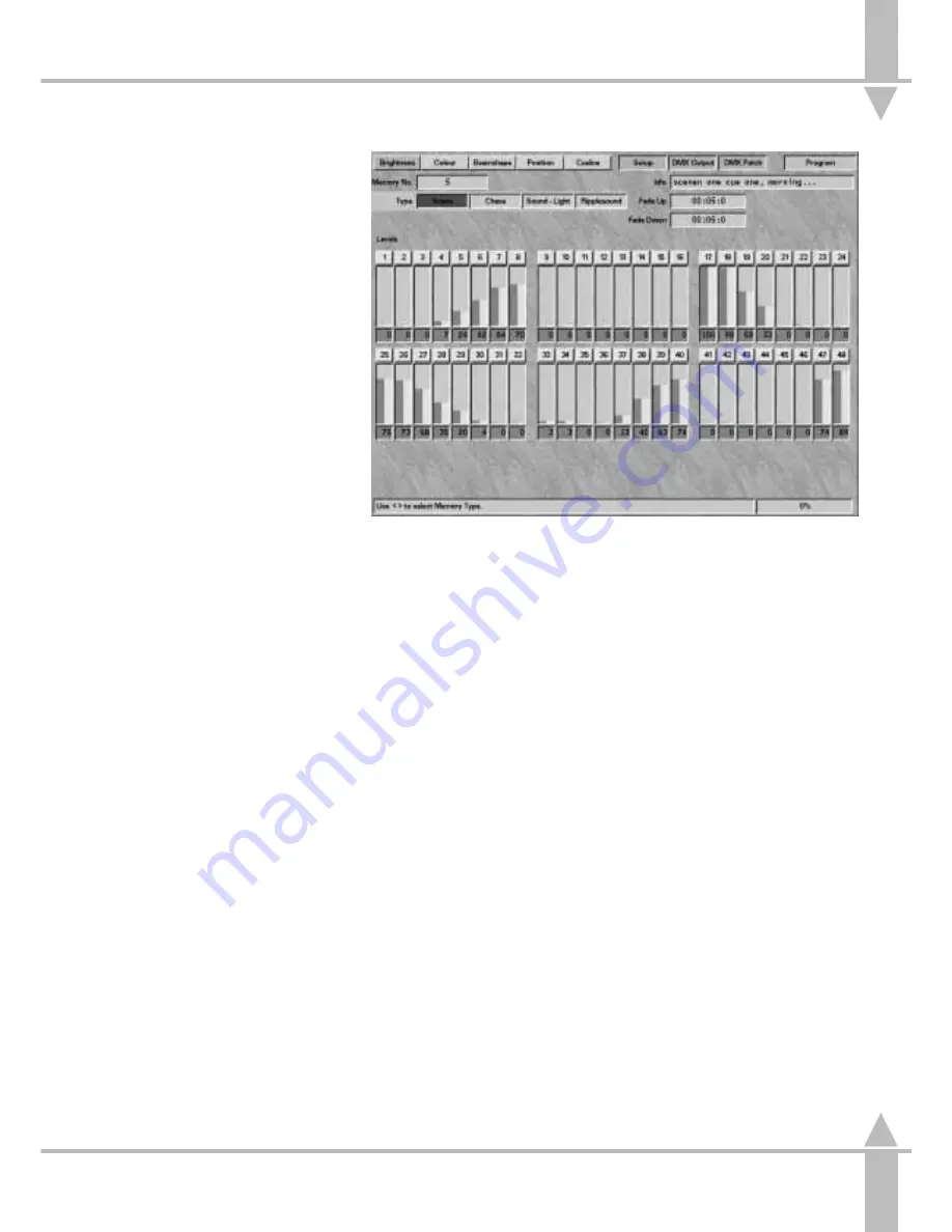
Top row on the monitor
the key switch position (Program) is
indicated in the top right-hand corner
of the screen. The boxes to the left
showing Brightness, Colour,
Beamshape, Position, CueLine,
Setup, DMX Output and DMX Patch.
Indicating which screen is active by
highlighting it in red as screens are
changed, and in green when active.
Normally Set-Up, DMX Output and
DMX Patch are shown in a different
green as they are only accessible via
the arrow keys, The other have
selection buttons by the wheels
:
Setting Up a Scene
The results of the preceding
instructions to set up a scene are
shown on the bar graph. Selected
fixtures are highlighted in red.
:
Programming
The PROGRAM button can be
pressed at any time to save the
current memory settings.
:
Channel Output
The bar graph showing channel
output is split vertically in two.
The green left half shows actual
output (see Figure 3-8), the yellow
right half shows levels programmed
into the current memory (see
Figure 3-9). Channels programmed
with PRESET faders cannot be
edited below the current fader level.
:
Inputting Text
Press the FLASH FUNCTION button
until TEXT is selected. The active bar
moves to Info. Input the text using
the channel flash buttons or the
external keyboard. Press the FLASH
FUNCTION button when finished to
return the active bar to the memory
number.
:
Level Adjustments
Level adjustments can be made at
any time.
:
Fade Times
Fade times can be adjusted at any
time and are displayed on the
monitor.
:
Output Level
Below each fader bar a small box
shows the current output level in
figures. This Box is yellow when the
output is the same as the stored
memory and changes to green if the
output is different to the stored
memory
:
Information
The bottom of the monitor screen
shows information and limited help
text.
:
Unlatched Channels
Brightness channels that are not
patched to the DMX outputs produce
a dark green bar graph display, and
the fixture number is gray not yellow.
Unpatched Brightness channels are
not recorded into memories,
therefore the yellow bars do not
appear when the PROGRAM button
is pressed.
/p3-9/3
Reviewing a Brightness Memory
1
Lower all submasters and
MASTER A and B to zero. Any
resulting DMX output (for
Brightness) emanates from the
current memory.
2
Use the [ and ] keys to change
the memory number to review
memory outputs.
3
Use the BLIND feature to remove
the current memory and Presets
from the DMX outputs, see the
section on Activating BLIND on
page 3-21. Any remaining
Brightness DMX signals are from
memories transferred to the
submasters.
n
Figure 3-9: Brightness screen (after saving)
3
Programming Memories
7364000/p3-9/3
3 - 9
Summary of Contents for SIRIUS 250
Page 1: ...SIRIUS 500 250 OPERATOR S MANUAL...
Page 3: ...ii...
Page 7: ...Pvi V3 TABLE OF CONTENTS vi 7364000 Pvi V3...
Page 15: ......
Page 30: ...p3 11 3 7364000 p3 11 3 3 11...
Page 57: ......
Page 67: ...p4 10 1...
Page 107: ......
Page 111: ......
Page 117: ......


