background image


01/2013  

Introduction to ZEN – Efficient Navigation 

The 

ZEN 2012

 Interface is clearly structured and follows the typical workflow of the experiments 

performed with confocal microscopy systems: 

On the 

Left Tool Area

 (Fig. 4/

D

) the user finds the tools for sample observation, image acquisition, 

image processing and system maintenance, easily accessible via four 

Main Tabs

 (Fig. 5/

1

). All functions 

needed to control the microscope can be found on the 

Locate 

tab, to acquire images use the 

Acquisition Tools

 (Fig. 5/

3

 and 

4

). Arranged from top to bottom they follow the logic of the 

experimental workflow. The area for viewing and interacting with images is centered in the middle of the 

Main Application 

window: the 

Center Screen Area

. Each displayed image can be displayed and/or 

analyzed with many view options available through view tabs which can be found on the left side of the 
image. According to the chosen view tab, the required view controls appear in View Control Tabs below 
each image. File management and data handling tools are found in the 

Right Tool Area

 (see Fig. 4 and 

Fig. 5). 

Color and brightness of the interface have been carefully adjusted to the typical light conditions of the 
imaging laboratory, guaranteeing optimal display contrast and minimal stray light for high-sensitivity 
detection experiments. The 

ZEN

 software is optimized for a 30" TFT monitor but can also be used with 

dual-20" TFT setups. 

A focus in the development of 

ZEN 2012

 was to fulfill the needs of both basic users and microscopy 

specialists. Both types of users will appreciate the set of intuitive tools designed to make the use of a 
confocal microscope from Carl Zeiss easy and fast. 
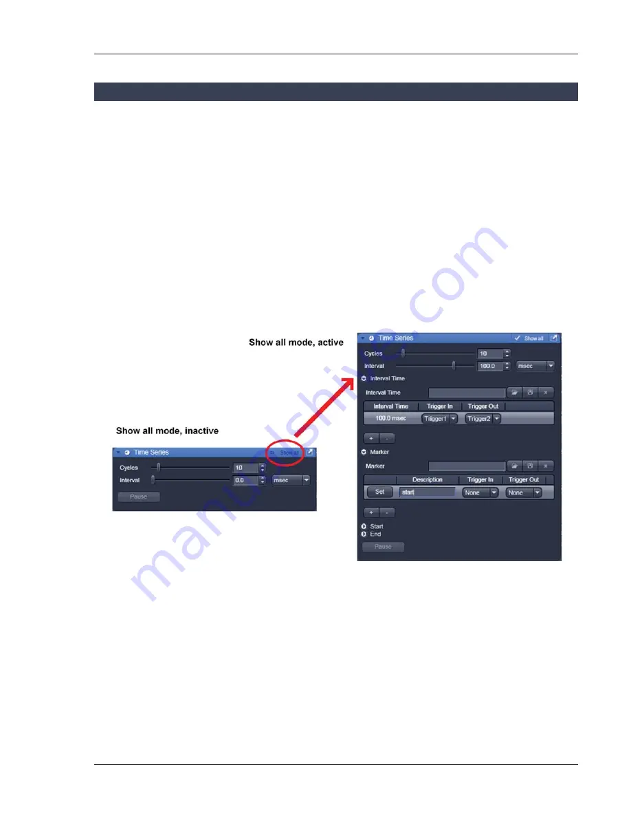
The 

Show all

 concept ensures that tool panels are never more complex than needed. With 

Show all 

de-

activated, the most commonly used tools are displayed. For each tool, the user can activate 

Show all 

mode to display and use additional functionality (Fig. 6). 


Fig. 6 

Show all mode 

Summary of Contents for LSM 700

Page 1: ...071 0EWIV 7GERRMRK 1MGVSWGSTI 071 7SJX EVI 2 ERYEV 1UICK UIDE M i c r o s c o p y f r o m C a r l Z e i s s...

Page 2: ......

Page 3: ...is Quick Guide does NOT replace the detailed information available in the full user manual or in the manual of the respective microscopes Axio Imager Axio Observer Also this Quick Guide is written for...

Page 4: ...laser The yellow LED in return turns on If this is not the case check the power switch Fig 2 2 on the back of the laser module x On the back of the system there is a plastic screw Fig 2 1 This is a l...

Page 5: ...activates the entire software package for new image acquisition and analysis The Image Processing mode ignores all hardware and activates only data handling and image processing functionality for alre...

Page 6: ...4 01 2013 Fig 4 ZEN Main Application window after startup with empty image container Fig 5 ZEN Main Application window after startup with several images loaded...

Page 7: ...the image According to the chosen view tab the required view controls appear in View Control Tabs below each image File management and data handling tools are found in the Right Tool Area see Fig 4 a...

Page 8: ...your personal preferences Fig 7 Setting up conventional confocal software for a specific experiment can take a long time and is often tedious to repeat With ZEN these adjustments have to be done only...

Page 9: ...will be over written by a new scan Multi dimensional scans or saved images will never be over written and a new scan will then automatically create a new image document Acquired data is not automatic...

Page 10: ...e File menu The File Browser can be used like the WINDOWS program file browser Images can be opened by double click and image acquisition parameters are displayed with the thumbnails Fig 9 For more in...

Page 11: ...he lasers are turned on automatically The Laser Life Extender function of the software shuts all lasers off if ZEN is not used for more than 15 minutes x To manually switch lasers on or off click the...

Page 12: ...ular tool active the specimen can be observed and all changes in the ocular tool take effect immediately When pressing the Oculars Offline button the system stays in the imaging mode Changes in the oc...

Page 13: ...ns will automatically move into the beam path Focusing the microscope for transmitted light x Open the graphical pop up menu by clicking on the Transmitted Light icon Fig 12 x Click on the On button S...

Page 14: ...configuration name in the pop up window confirm the name by clicking OK Fast restoration of a saved configuration is achieved by selecting the configuration from the pull down list The configuration i...

Page 15: ...he arrow in the dye list and simply choose the dye s you want to use in your experiment from the list dialogue In this dialogue the dyes can be also searched by typing the name in the search field Fig...

Page 16: ...14 01 2013 Fig 15 Proposals panel of the Smart Setup tool...

Page 17: ...ed icon will be highlighted If the motif Current is clicked the current set of scanning parameters will be left untouched x Pressing the Apply button applies the selected proposal in Smart Setup as we...

Page 18: ...ge acquisition Disadvantage cross talk between channels Sequential scanning of double and triple labeling line by line or frame by frame Advantage Only one detector and one laser are switched on at an...

Page 19: ...b choose the suitable emission filters for the dye combination entered for PMT 1 and PMT 2 x The emission spectra and the laser lines used of the selected dyes are displayed in the light path tool x C...

Page 20: ...nged between tracks Laser line and intensity all filters and beam splitters the channels incl settings for gain and offset and the pinhole position and diameter Frame Fast The scanning procedure can b...

Page 21: ...Acquisition Mode tool Fig 20 to adjust the scan speed A higher speed with averaging results in the best signal to noise ratio Scan speed 8 usually produces good results Use speed 6 or 7 for superior...

Page 22: ...ode in the Acquisition Mode tool x Select the number of lines or frames to average Adjusting pinhole x Select the Channels tool in the Left Tool Area x Set the Pinhole size to 1 AU Airy unit for best...

Page 23: ...Set Exposure for automatic pre adjustment of detector gain and offset Select Live for continuous fast scanning useful for finding and changing the focus Select Continuous for continuous scanning with...

Page 24: ...een Blue zero minimum Adjusting the laser intensity x Set the Pinhole to 1 AU Airy Unit Fig 25 x Set the Gain high x When the image is saturated Laser Power in the Laser control section of the Channel...

Page 25: ...lower specimen area where the recording of the Z Stack is to end x Click on the Set Last button to set this lower position x Click on the button to set number of slices to match the optimal Z interval...

Page 26: ...available extra information and hardware settings of your experiment x Click on the Save button If you close an image which has not been saved a pop up window will ask you if you want to save it Choo...

Page 27: ...h Fig 1 1 of the laser module to the left in the off position x If using the Axio Observer microscope stand push the power button at the left hand side to switch off the microscope x Turn off the LSM...

Reviews: