background image


01/2013  

17 


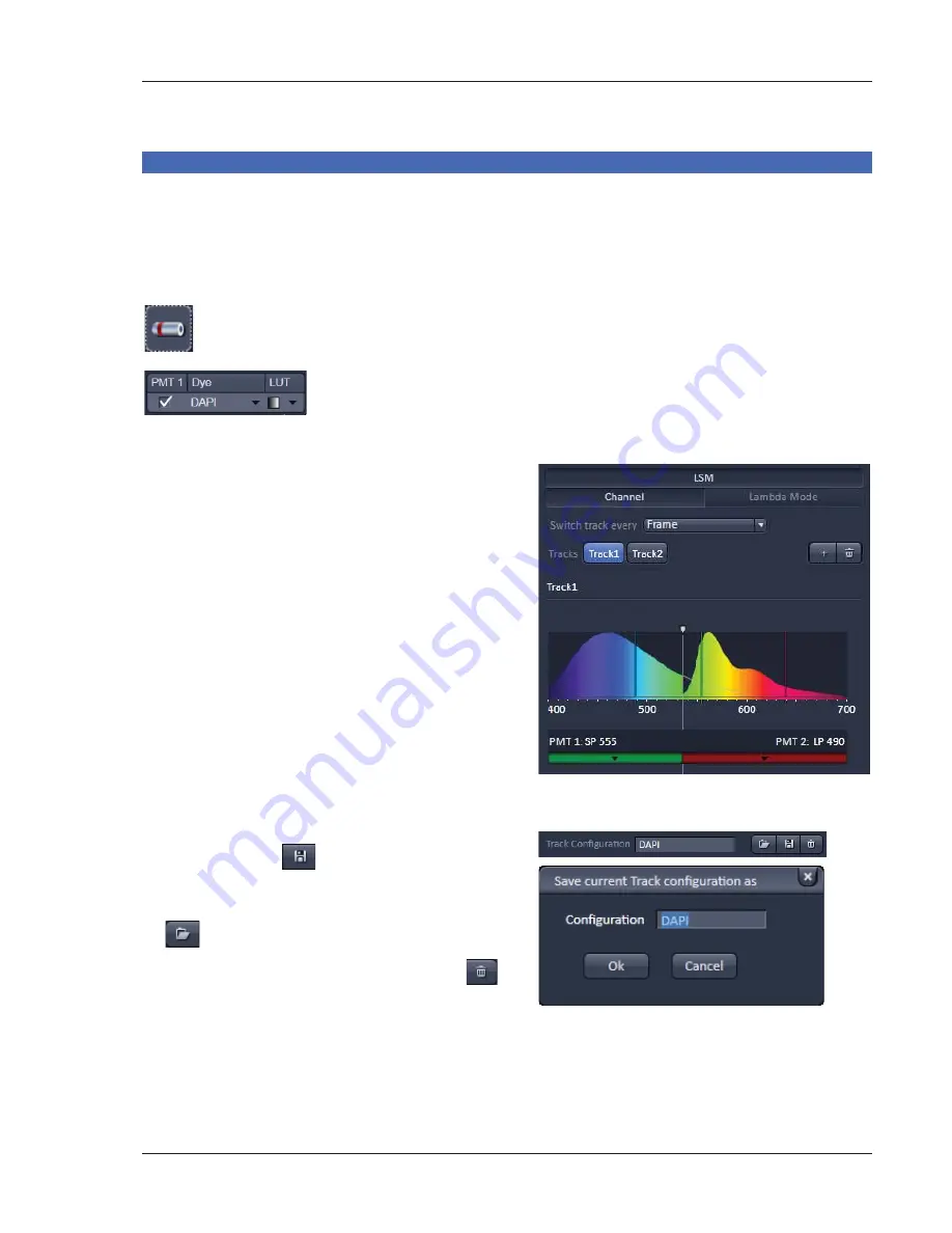
Settings for track configuration in Channel mode 

x


Select 

Channel 

mode if necessary (Fig. 17). 

x


Click on the 

LSM

 button in the light path tool (Fig. 17). 

The 

Light Path 

tool displays the selected track configuration which is used for the scan procedure. 

x


You can change the settings of the light path tool using the following functional elements: 


Activation / deactivation of the excitation wavelengths (check box) and 
setting of excitation intensities (slider). If necessary open the 

Laser Control 

tool (see above). 


Activation / deactivation (via check box) of a channel (

PMT1

2

), the dye to 

be detected with this channel (

dye

), and a color for display (

LUT

) of the 

acquired information.  


x


The system will automatically: a) select the most 
appropriate position of the secondary dichroic 
mirror and b) choose the suitable emission 
filters for the dye combination entered for 
PMT 1 and PMT 2. 

x


The emission spectra and the laser lines used of 
the selected dyes are displayed in the light path 
tool.  

x


Click the 

Laser

 icon to select the laser lines and 

set the attenuation values (transmission in %) in 
the light path tool. 

x


The Detection Bands & Laser Lines are also 
displayed in a spectral panel (Fig. 18) to visualize 
the activated laser lines for excitation (vertical 
lines) and activated detection channels (colored 
horizontal bars). 

x


For storing a new track configuration open the 

Channels

 tool in the 

Acquisition Parameter


tool group, click 

 and enter a desired name 

in the box (Fig. 19). Press 

OK

 to confirm. 

x


For loading an existing configuration click on 

 and select a configuration from the list box. 

x


For deleting an existing configuration click 


and select it from the list box. Press 

Ok

 to 

confirm the deletion. 


Fig. 18 

Detection bands & Laser lines 
display 


Fig. 19 

Track Configurations window 


Summary of Contents for LSM 700

Page 1: ...071 0EWIV 7GERRMRK 1MGVSWGSTI 071 7SJX EVI 2 ERYEV 1UICK UIDE M i c r o s c o p y f r o m C a r l Z e i s s...

Page 2: ......

Page 3: ...is Quick Guide does NOT replace the detailed information available in the full user manual or in the manual of the respective microscopes Axio Imager Axio Observer Also this Quick Guide is written for...

Page 4: ...laser The yellow LED in return turns on If this is not the case check the power switch Fig 2 2 on the back of the laser module x On the back of the system there is a plastic screw Fig 2 1 This is a l...

Page 5: ...activates the entire software package for new image acquisition and analysis The Image Processing mode ignores all hardware and activates only data handling and image processing functionality for alre...

Page 6: ...4 01 2013 Fig 4 ZEN Main Application window after startup with empty image container Fig 5 ZEN Main Application window after startup with several images loaded...

Page 7: ...the image According to the chosen view tab the required view controls appear in View Control Tabs below each image File management and data handling tools are found in the Right Tool Area see Fig 4 a...

Page 8: ...your personal preferences Fig 7 Setting up conventional confocal software for a specific experiment can take a long time and is often tedious to repeat With ZEN these adjustments have to be done only...

Page 9: ...will be over written by a new scan Multi dimensional scans or saved images will never be over written and a new scan will then automatically create a new image document Acquired data is not automatic...

Page 10: ...e File menu The File Browser can be used like the WINDOWS program file browser Images can be opened by double click and image acquisition parameters are displayed with the thumbnails Fig 9 For more in...

Page 11: ...he lasers are turned on automatically The Laser Life Extender function of the software shuts all lasers off if ZEN is not used for more than 15 minutes x To manually switch lasers on or off click the...

Page 12: ...ular tool active the specimen can be observed and all changes in the ocular tool take effect immediately When pressing the Oculars Offline button the system stays in the imaging mode Changes in the oc...

Page 13: ...ns will automatically move into the beam path Focusing the microscope for transmitted light x Open the graphical pop up menu by clicking on the Transmitted Light icon Fig 12 x Click on the On button S...

Page 14: ...configuration name in the pop up window confirm the name by clicking OK Fast restoration of a saved configuration is achieved by selecting the configuration from the pull down list The configuration i...

Page 15: ...he arrow in the dye list and simply choose the dye s you want to use in your experiment from the list dialogue In this dialogue the dyes can be also searched by typing the name in the search field Fig...

Page 16: ...14 01 2013 Fig 15 Proposals panel of the Smart Setup tool...

Page 17: ...ed icon will be highlighted If the motif Current is clicked the current set of scanning parameters will be left untouched x Pressing the Apply button applies the selected proposal in Smart Setup as we...

Page 18: ...ge acquisition Disadvantage cross talk between channels Sequential scanning of double and triple labeling line by line or frame by frame Advantage Only one detector and one laser are switched on at an...

Page 19: ...b choose the suitable emission filters for the dye combination entered for PMT 1 and PMT 2 x The emission spectra and the laser lines used of the selected dyes are displayed in the light path tool x C...

Page 20: ...nged between tracks Laser line and intensity all filters and beam splitters the channels incl settings for gain and offset and the pinhole position and diameter Frame Fast The scanning procedure can b...

Page 21: ...Acquisition Mode tool Fig 20 to adjust the scan speed A higher speed with averaging results in the best signal to noise ratio Scan speed 8 usually produces good results Use speed 6 or 7 for superior...

Page 22: ...ode in the Acquisition Mode tool x Select the number of lines or frames to average Adjusting pinhole x Select the Channels tool in the Left Tool Area x Set the Pinhole size to 1 AU Airy unit for best...

Page 23: ...Set Exposure for automatic pre adjustment of detector gain and offset Select Live for continuous fast scanning useful for finding and changing the focus Select Continuous for continuous scanning with...

Page 24: ...een Blue zero minimum Adjusting the laser intensity x Set the Pinhole to 1 AU Airy Unit Fig 25 x Set the Gain high x When the image is saturated Laser Power in the Laser control section of the Channel...

Page 25: ...lower specimen area where the recording of the Z Stack is to end x Click on the Set Last button to set this lower position x Click on the button to set number of slices to match the optimal Z interval...

Page 26: ...available extra information and hardware settings of your experiment x Click on the Save button If you close an image which has not been saved a pop up window will ask you if you want to save it Choo...

Page 27: ...h Fig 1 1 of the laser module to the left in the off position x If using the Axio Observer microscope stand push the power button at the left hand side to switch off the microscope x Turn off the LSM...

Reviews: