


18
01/2013
Settings for multiple track configurations in Channel Mode
Multiple track
set-ups for sequential scanning can be defined as one configuration (
Channel Mode
Configuration
), to be stored under any name, reloaded or deleted.
The maximum of four tracks with up to three channels can be defined simultaneously and then scanned
one after the other. Each track is a separate unit and can be configured independently from the other
tracks with regard to channels, Acousto-Optical Tunable Filters (AOTF), emission filters and dichroic beam
splitters.
The following functions are available in the
Light Path
tool of the
Setup Manager
tool group
(Fig. 17,
Fig. 18 and Fig. 19).
Switch track
every
selection box
Line
Tracks are switched during scanning line-by-line. The following settings can be changed
between tracks: Laser line, laser intensity and channels.
Frame
Tracks are switched during scanning frame-by-frame. The following settings can be
changed between tracks: Laser line and intensity, all filters and beam splitters, the
channels incl. settings for gain and offset and the pinhole position and diameter.
Frame Fast
The scanning procedure can be made faster. Only the laser line intensity is switched, but
no other hardware components. The tracks are all matched to the current track with
regard to emission filter, dichroic beam splitter, setting of Detector Gain, pinhole
position and diameter. When the
Line
button is selected, the same rules apply as for
Frame Fast
.
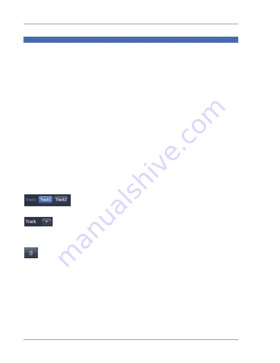
Tracks line
Track
buttons: To change between the tracks settings click on the
appropriate track button. The selected track is highlighted. The setting table
for configuration will be shown behind.
Add Track
button: An additional track is added to the configuration list in
the
Imaging Setup
tool. The maximum of four tracks can be used. One track
each with basic configuration is added, i.e.: Ch 1 channel is activated, all laser
lines are switched off, emission filters and dichroic beam splitters are set in
accordance with the last configuration used.
Remove
button: The track marked in the
List of Tracks
panel is deleted.
Summary of Contents for LSM 700
Page 2: ......
Page 16: ...14 01 2013 Fig 15 Proposals panel of the Smart Setup tool...


