Zeiss Axioscope 7, Operating Manual
The Zeiss Axioscope 7 is a high-quality microscope designed for precise imaging in scientific research. Ensure optimal performance by referring to the Operating Manual available for free download from manualshive.com. This comprehensive manual provides step-by-step instructions for maximizing the capabilities of this advanced instrument.
Share
Download


Reviews:
No comments
Related manuals for Axioscope 7

U-FWO
Brand: Olympus Pages: 12

S90007 Series
Brand: Fisher Scientific Pages: 4

ZOOM 2000
Brand: Leica Pages: 12
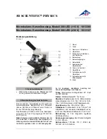
300 LED 1013366
Brand: 3B SCIENTIFIC PHYSICS Pages: 12

54949
Brand: CEN-TECH Pages: 8

104-CLED
Brand: National Pages: 6

106
Brand: National Pages: 8

D1 Series
Brand: BMS Pages: 18

MED PRO 600 Fluo
Brand: Levenhuk Pages: 128

PZ-4
Brand: M2 Pages: 13

P-400R
Brand: Nikon Pages: 115

BHSP
Brand: Olympus Pages: 22

L-ke
Brand: Nikon Pages: 13

HDZ7000TS Series
Brand: Meiji Techno Pages: 14

MT7000 series
Brand: Meiji Techno Pages: 28

MT7500 series
Brand: Meiji Techno Pages: 28

MI-5000STD
Brand: HomeScienceTools Pages: 8

BXFM Series
Brand: Olympus Pages: 36


