background image

CT200-G1 User Guide

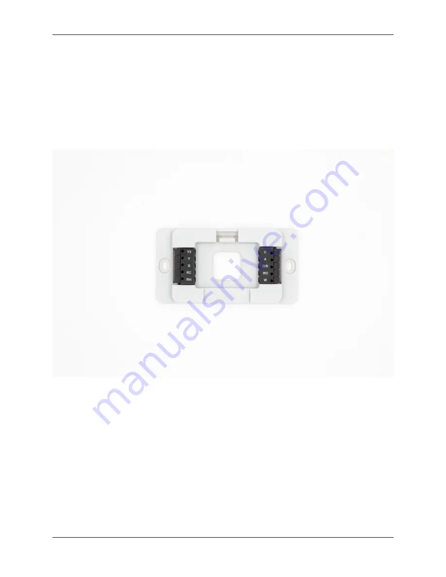
Mounting Plate

1. Carefully pull the labeled wires through the center hole in the Mounting Plate.

2. Position Thermsotat for best appearance to cover the hole in the wall.

3. Mark first and drill a 1⁄4 in. (6mm) hole at each screw location.

4. If you are mounting the Thermostat to sheet rock or if you are using the old mounting holes, use the

plastic anchors provided.

5. Attach the Mounting Plate to the wall with the screws provided.

Fig. 3: Thermostat Mounting Plate

4

Chapter 1. Installation Guide

Summary of Contents for CT200-G1

Page 1: ...CT200 G1 User Guide Radio Thermostat Jul 29 2019 ...

Page 2: ......

Page 3: ...1 Installation Guide 1 Getting Started 1 Wiring 3 Wiring Diagrams 8 Wire Reference Table 12 2 Operation Guide 15 Product Overview 15 Device Menu 16 Configure Menu 17 Thermostat Warnings 18 3 Z Wave Reference 19 i ...

Page 4: ...ii ...

Page 5: ...s a precise instrument All wiring must conform to local codes and ordinances Use with 4AA alkaline batteries and or 24 volt AC C wire or a 12 24 AC or DC source or millivolt gas systems Each thermostat relay load should be limited to 1 0 amp Higher amperage can cause damage to the thermostat Tools needed for installation include Screwdriver Small Phillips screwdriver Drill with 1 4 bit 6 mm Locati...

Page 6: ...horten the thermostat s life Do not locate where air circulation is poor such as a corner an alcove or behind an open door Do not install the thermostat until all construction and painting is complete This thermostat does not require leveling Tip Locate the thermostat in place of the previous thermostat to avoid having to move wiring to a new location Fig 1 Recommended Installation Location 2 Chap...

Page 7: ...e the cover from the existing thermostat Check for locking screws on the side or front that must be loosened first 3 Attach provided labels to each wire for identification Refer to the lettered terminal where the wires attach do not use the color of the wires 4 Disconnect wires from the existing thermostat and wind them around a pencil to keep them from falling back inside the wall 5 Loosen all moun...

Page 8: ...rance to cover the hole in the wall 3 Mark first and drill a 1 4 in 6mm hole at each screw location 4 If you are mounting the Thermostat to sheet rock or if you are using the old mounting holes use the plastic anchors provided 5 Attach the Mounting Plate to the wall with the screws provided Fig 3 Thermostat Mounting Plate 4 Chapter 1 Installation Guide ...

Page 9: ...for safe and secure wire connections Use at least 3 inches of wire for each of your connections to the Thermostat Splice additional wire to allow enough slack Use 16 22 awg for connection to thermostat terminal blocks Remove approximately 1 8 inch of insulation from the tip of each wire Take care not to damage the labels for each wire If you have both RH and RC connections you must set the RC RH S...

Page 10: ...l installations The Thermostat can be externally powered with a power source rated from 12V to 24V AC or DC at 100ma or greater If used connect to the C and RH terminals no polarity The 24VAC C wire is the other side of the 24VAC heating transformer and can be found where the other thermostat wires connect at the wall or at the furnace Do not use the common or ground side of the line voltage The T...

Page 11: ...e Do not dispose of batteries in fire Batteries may explode or leak Always replace the batteries as soon as the Low Batt warning flashes The thermostat is a battery powered device you should replace the batteries before they run out as failure to replace batteries can result in excessive heating or cooling of your house Always replace the batteries once a year even if the Low Batt indicator does not...

Page 12: ... the RH terminal Heat Power 2 Connect the W wire to the W terminal Heat 3 Connect the G wire to the G terminal Fan 4 If available connect the C wire to the C terminal Fig 5 Four wire HVAC system 5 Wire Heat Cool for systems with HEAT and COOL and shared power 1 Connect the W wire to the W terminal Heat 2 Connect the Y wire to the Y terminal Cooling compressor 3 Connect the RH or R wire to the RH t...

Page 13: ... the G terminal Fan 6 If available connect the C wire to the C terminal Fig 7 Six wire HVAC system Multi stage Heat Cool for systems with up to 2 stages of HEAT and 2 stages of COOL 1 Connect the W and W2 wires to the W and W2 terminals Heat 2 Connect the Y and Y2 wires to the Y and Y2 terminals Cool 3 Connect the RH or R wire to the RH terminal Power 4 Connect the G wire to the G terminal Fan 5 I...

Page 14: ...compression and 2 stages of AUX heat Warning If you have both O and B connect only the O wire to the O terminal and DO NOT connect B to B terminal 1 Connect O wire to the O terminal or the B wire to the B terminal Change over Valve 2 Connect the AUX 1 wire to the AUX 1 terminal 1st stage Auxiliary Heat 3 Connect the AUX 2 wire to the AUX 2 terminal 2nd stage Auxiliary Heat 4 Connect the Y and Y2 w...

Page 15: ...ting system configure the thermostat as HVAC Type Radiant with Heat Type Gas Use Thermostat only in Heat Mode The Thermostat must be powered by 24VAC The third wire on your valve may be called 6 Y or G see the Wire Reference Table Fig 11 Hot Water HVAC system Wiring Diagrams 11 ...

Page 16: ...d stage COOL or compression for a heat pump G F G FAN control C X C 24VAC power to power thermostat H H External Humidifier DH DH External De Humidifier EX EX External fresh air baffle B B Heat pump changeover cool to heat powered in heat O O Heat pump changeover heat to cool powered in cool B and O WARNING E n a Emergency heat do not connect tape off L n a System monitor do not connect tape off T n ...

Page 17: ...t HVAC Systems System Label RTCOA HVAC Function Zoned Hot Water 2 Wire R RH W W Motor Driven Valves 3 Wire R 5 RH Power W 4 W HEAT ON Y G 6 A HEAT OFF Solenoid Valves 3 Wire R RH Power W A HEAT ON Y G W HEAT OFF Wire Reference Table 13 ...

Page 18: ...CT200 G1 User Guide 14 Chapter 1 Installation Guide ...

Page 19: ...ss to change the target temperature Change Thermostat Mode Press the side button once then Press to select mode Fan Screen enables you to change fan operation and set the fan timer View Screen Press the SIDE button twice Outside Weather Screen displays the outside temperature and outside humidity View Screen Press and Hold the side button until screen appears then release Change Screen Press to to...

Page 20: ...emaining battery power HVAC Configuration type of heating and cooling Relays the active wires being used by the system Network Z Wave Network connection status Software versions for Thermostat D and Z Wave Z Testing runs heating or cooling for up to 30 minutes as a system test You can stop a test at any time by selecting Stop and pressing the side button If Thermostat is con figured for Heat Pump th...

Page 21: ... offsets the temperature measurement Calibration range is 5 0 to 5 0 degrees Cycling sets an offset to the current room temperature before the heating or cooling system will turn on The Cycling can be from 0 5F to 4 0F For example if Cycling is set to 2 0F and the Thermostat is set to 70F target temperature the heat cycle will start when the room temperature drops to 68F Similarly the cooling syst...

Page 22: ...inate Warning Replace the batteries 1 Turn the thermostat mode to OFF from heat or cool 2 Remove Thermostat from mounting plate 3 Replace the batteries 4 Replace Thermostat to mounting plate 5 Adjust the thermostat mode as desired Your settings will be retained and the thermostat will automatically reconnect to the Z Wave Network Network Disconnected Warning indicates the thermostat has lost the c...

Page 23: ...board radio that can be added to an existing Z Wave network This device can be used on a network with products from different vendors Alternative to SmartStart the thermostat can be added by 1 Set your primary controller to INCLUDE mode to add the thermostat as a node on your network see your specific controller s User Manual for detailed instructions 2 The thermostat main screen shows a welcome me...

Page 24: ... it is included to the Z Wave network if the C Wire is present and powered when including to the network the thermostat will remain an always listening node until it is removed from the network Security 2 is suppored by this device Table 1 Supported Command Classes Category Command Class Security Level Application Basic n a Application Configuration Authenticated Application Multilevel Sensor Authe...

Page 25: ...s follow Basic Set Value 0x00 Set Energy Saving Mode Basic Set Value 0xFF Set Comfort Mode Configuration Command Class is supported by this device The Configuration Command Class allows product specific configuration parameters to be changed Table 2 Summary of Configuration Parameters Parameter 8 bit Name 0x01 Temperature Reporting Threshold 0x02 HVAC Settings 0x03 Utility Lock 0x04 Thermostat Power So...

Page 26: ...Disable Reporting 0x01 0 5 degrees Fahrenheit 0x02 1 0 degrees Fahrenheit DEFAULT 0x03 1 5 degrees Fahrenheit 0x04 2 0 degrees Fahrenheit HVAC Settings Get Only The HVAC Settings parameter contains a read only description of the HVAC settings of the thermostat Table 5 HVAC Settings Name Value Parameter 8 bit 0x02 Size 3 bit 0x04 Configuration Values 32 bit Byte N Upper Nibble Lower Nibble Byte 1 Co...

Page 27: ... the user on the thermostat physical user interface Table 7 Utility Lock Name Value Parameter 8 bit 0x03 Size 3 bit 0x01 Configuration Values 8 bit Lock State Configuration values are bit encoded Unsupported values will be ignored Table 8 Lock State Value Configuration 0x00 Disabled lock DEFAULT 0x01 n a 0x02 n a 0x03 Enabled lock Thermostat Power Source Get Only The Thermostat Power Source parameter...

Page 28: ...ameter enables or disables Thermostat Mode called Auxiliary Heating in the thermostat while the thermostat mode is Heat Enabling Auxiliary Heat parameter will only use the auxiliary heating HVAC subsystem to maintain the room temperature using the thermostat heating setpoint The heat pump will not be used to maintain the room temperature Auxiliary heating is only available if the thermostat is con...

Page 29: ...heit 0x02 1 0 degrees Fahrenheit DEFAULT 0x03 1 5 degrees Fahrenheit 0x04 2 0 degrees Fahrenheit 0x05 2 5 degrees Fahrenheit 0x06 3 0 degrees Fahrenheit 0x07 3 5 degrees Fahrenheit 0x08 4 0 degrees Fahrenheit Thermostat Differential The Thermostat Differential Temperature parameter specifies the differential temperature for multi stage HVAC systems The Configuration Set Command is used to set the va...

Page 30: ... 8 bit 0x08 Size 3 bit 0x02 Configuration Values 16 bit Byte 1 Heating Differential Tempera ture Byte 2 Cooling Differential Tempera ture Warning Unlike the Set Command the Configuration Report returns the Differential Temperature for both the Heat Mode and Cool Mode The Configuration Report does not explicitly return the Differential Mode Thermostat Recovery Mode The Thermostat Recovery Mode paramet...

Page 31: ...o The Configuration Set Command is used to set the value of a configuration parameter Table 23 Thermostat Recovery Mode Set Command Name Value Parameter 8 bit 0x0A Default Value 1 bit If set then Disabled using Upper Bound 0F Lower Bound 124F Size 3 bit 0x04 Configuration Values 32 bit Byte 1 Lower Bound Temperature Scale Byte 2 Lower Bound Temperature Fil ter Byte 3 Upper Bound Temperature Scale Byt...

Page 32: ...ing the thermostat a Get request for this parameter will cause the thermostat to respond with a Configuration Report containing the original time it was set to When the Fan Timer value is changed through the Thermostat s UI this parameter will be sent to the association group as an unsolicited message The valid values for this parameter are listed below Table 27 Fan Timer Name Value Parameter 8 bit...

Page 33: ...00 0 0 degree Fahrenheit DEFAULT 0x01 00000001 1 0 degree Fahrenheit 0x02 00000010 2 0 degree Fahrenheit 0x03 00000011 3 0 degree Fahrenheit 0x04 00000100 4 0 degree Fahrenheit 0x05 00000101 5 0 degree Fahrenheit 0x06 00000110 6 0 degree Fahrenheit Warning The offset must be an integer value Non integer values such as 1 5F 0x03 should not be used Display Units The Display Units parameter specifies ...

Page 34: ...oes cause harmful interference to radio or television reception which can be determined by turning the equipment off and on try to correct the interference by following these suggestions Reorient or relocate the receiving antenna Increase the separation between the equipment and receiver Connect the equipment to an outlet on a circuit different from that to which the receiver is connected Consult ...

Reviews: