background image

Spectrum Z™510 3D Printer Hardware Manual

Using the ZPrint Firmware and Software

www.3dpuser.com

30

10/2/07

All Rights Reserved

Slice viewing allows you to view the cross sections of the part to identify any errors in the file. 

Collision detection will scan through the slices and report the layer in which part overlapping is found. 

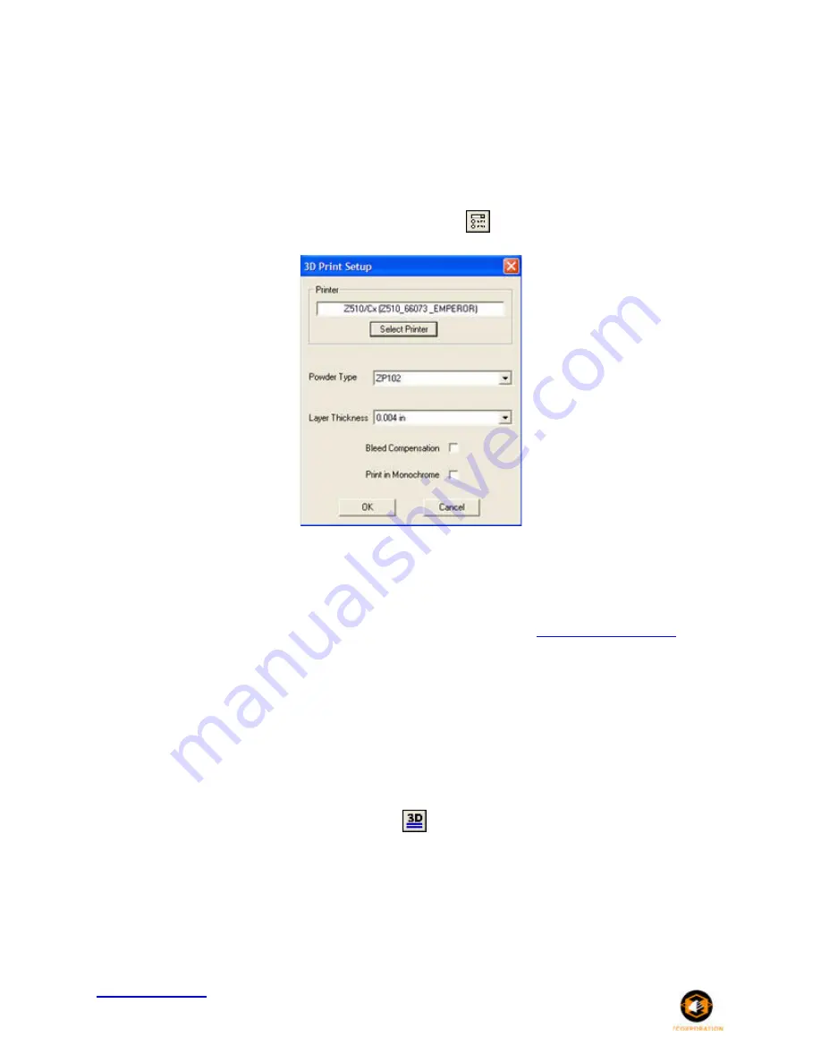
Follow the steps below to check your build settings.

1. Choose the 

3D Print Setup

 on the 

File

 menu, or click the 

 icon on the Toolbar. 

2. Check that the selected printer, powder type, and powder settings for the build are correct.  The soft-

ware settings are the recommended values. 

3. If the settings need to be changed, select 

Override

. Press 

OK

 to confirm. 

For more information on how to change these settings, please refer to the 

ZPrint Software Manual

6.7 Printing the Build

It is strongly recommended that the build settings be confirmed before printing. To check build settings, 
choose 

3D Print Setup

 on the 

File

 menu or click on the icon located on the taskbar. After all build settings 

have been confirmed: 

1. Choose 

3D Print

 on the 

File

 menu, or click the 

 icon on the Toolbar.

 
2. A dialog box will appear asking that powder and fluid levels be checked. Check off the boxes to con-

firm that these have been inspected before beginning the build. 

3. Once the build has begun, a dialog box will appear reporting the status of the build.

Summary of Contents for Spectrum Z 510

Page 1: ...www 3dpuser com All Rights Reserved 10 2 07 Spectrum Z 510 3D Printer Hardware Manual Rev J Part Number 09537 August 2007...

Page 2: ...5 Routine Operations 20 5 1 Preparing the Build Area 20 5 2 Cleaning the Service Station 22 5 3 Checking Fluid Levels 24 6 Using the ZPrint Firmware and Software 27 6 1 Firmware Overview 27 6 2 Insta...

Page 3: ...59 8 19 Printer Storage Preparation 59 8 19 1 Replace Fluid Lines with Distilled Water 59 8 20 Best Practices for Powder Management 60 9 Troubleshooting 61 9 1 The binder solution is being applied in...

Page 4: ...efend and hold Z Corporation and its officers directors and employees harmless from and against any and all claims losses damages costs and expenses resulting from any use of the Equipment other than...

Page 5: ...in how to use the most common infiltrants available from Z Corporation For information on other infiltrants or applications visit the 3DP User Website at www 3dpusers com ZPrint Service Menu and Other...

Page 6: ...e of maintenance is required a message is displayed in the ZPrint software and on the printer control panel Click 3D Printers to go to our 3DP User Website and download firmware for the Z510 Printer S...

Page 7: ...w in the up position Also represented in the diagrams are the roller drawn as a circle and the print assembly drawn as a square On the printer the roller and the print assembly are mounted together on...

Page 8: ...se the powder layers support the structures being printed the printer creates parts without support structures and will print parts with complex geometries that are impossible for other systems There...

Page 9: ...s discussion only applies to untreated parts once parts are infiltrated they uniformly take on the strength characteristics of the infiltrating mate rial Accuracy The accuracy of the system depends on...

Page 10: ...Spectrum Z 510 3D Printer Hardware Manual Introduction www 3dpuser com 7 10 2 07 All Rights Reserved 3 2 System Components 3 3 Printer Components Z510 3D Printer ZD5 Powder Recycling System...

Page 11: ...trum Z 510 3D Printer Hardware Manual Introduction www 3dpuser com 8 10 2 07 All Rights Reserved 3 4 Printer Control Panel 3 5 Internal Printer Assembly and Service Station Components Internal Compone...

Page 12: ...Spectrum Z 510 3D Printer Hardware Manual Introduction www 3dpuser com 9 10 2 07 All Rights Reserved Printer Assembly with Carriage Insert Service Station...

Page 13: ...r Hardware Manual Introduction www 3dpuser com 10 10 2 07 All Rights Reserved 3 6 ZD5 Powder Recycling System Click ZD5 Depowder Unit to see the User Manual for this unit and other accessories availab...

Page 14: ...High Performance Powder Improves on the properties of zp 102 with up to 8x increase in early strength 25 faster print times Prints finer details richer colors and a better surface finish Accurately r...

Page 15: ...Cure process Water Cure The easiest and safest post processing available Only tap water is required to seal and strengthen your printed parts and it has the lowest cost per in Vivid Colors zp140 deliv...

Page 16: ...tructions Service Form Documents to be com pleted and returned to Z Corp 1 Scraper 5 Wide Utility 2 Brush Double Ended 3 Brush 2 China Bristle 4 Brush Acid 5 Brush Toothbrush Style 6 Scraper 3 Wide Ut...

Page 17: ...cuum hose and attaches to the side of the feed box to capture airborne powder when powder is being added to the feed box 3 9 ZPrint Software Installation The ZPrint Software is the file processing too...

Page 18: ...d explanation see Routine Operations Using the ZPrint Firmware and Software and Post Process ing the Part 4 1 Preparing The 3D Printer 1 Fill the feed box with powder 2 With the printer offline spread...

Page 19: ...Check the binder bottles Fill if necessary 5 Check the wash fluid and the waste fluid Fill the wash fluid and dispose of the waste fluid 6 Put printer online by pressing the Online button on the cont...

Page 20: ...Printer Hardware Manual Quick Start Guide www 3dpuser com 17 10 2 07 All Rights Reserved 4 2 Preparing the Build in ZPrint Software 1 Launch ZPrint and open or import your file s 2 Orient and scale t...

Page 21: ...r Type and Layer Thickness options 4 Select 3D Print on the File Menu or click the 3D icon on the Toolbar Choose your settings in the Printing Options dialog and click OK Proceed through the series of...

Page 22: ...Spectrum Z 510 3D Printer Hardware Manual Quick Start Guide www 3dpuser com 19 10 2 07 All Rights Reserved 3 Fine depowder part and post process as needed...

Page 23: ...and will void warranty of equip ment 1 Preheat printer if needed Preheating the printer will reduce the print time if the printer has not reached the required temperature To preheat the printer selec...

Page 24: ...n will expose the build plate hold ers 7 Place build plate on top of holders Make sure build plate is secure Press any button on the control panel to lower the build piston 8 Fill the feed box with po...

Page 25: ...o keep powder dry Scoop powder carefully to minimize airborne powder Make sure that you carefully vacuum up excess powder It only takes a minute and the tidier the machine is the less often it will ne...

Page 26: ...h paper towel PLEASE NOTE Make sure the Parking Caps are sitting flat in their holders 3 Clean squirt manifold holes by carefully inserting the luer lock needle into the squirt manifold holes DO NOT P...

Page 27: ...r com 24 10 2 07 All Rights Reserved 5 Wipe metal spit cover with damp paper towel 6 Close top cover and press OK to repark on the software 5 3 Checking Fluid Levels 1 Open front cabinet tray 2 Check...

Page 28: ...der bottles The Z510 3D Printer is not equipped with binder level sensors The user must check the binder levels prior to each build to ensure the Z510 3D Printer has enough to complete the build View...

Page 29: ...s Reserved Refer to the following links to learn about other periodic maintenance tasks The following tasks should only be performed when prompted to by ZPrint or when you see a message on your 3D Pri...

Page 30: ...ew seconds PLEASE NOTE Make sure you install the firmware on the computer that is connected to your 3D Printer and that the printer is Online Click 3D Printer to locate the latest version of firmware...

Page 31: ...features under 0 050 1 27 mm Enabling bleed compensation may reduce the feature size To increase the strength of thin parts you can decrease the layer thickness to 0 0035 0 089 mm if you are using hi...

Page 32: ...ore fluid in the build For increased accuracy the software provides a fixture feature that creates a cradle for the overhanging area Cylindrical features will be more accurate when their axis is paral...

Page 33: ...ngs are the recommended values 3 If the settings need to be changed select Override Press OK to confirm For more information on how to change these settings please refer to the ZPrint Software Manual...

Page 34: ...Spectrum Z 510 3D Printer Hardware Manual Using the ZPrint Firmware and Software www 3dpuser com 31 10 2 07 All Rights Reserved...

Page 35: ...ce of breaking a part that is hidden beneath the surface of the powder While fine depowdering always start with a low air pressure and gradually increase the pressure as the fine details and features...

Page 36: ...step Stiff Detailing Brush This brush has very stiff bristles which is useful for scrubbing caked powder out of tight areas of a part The brush is also used for removing fringing from color part surfa...

Page 37: ...e button and lift the top cover 3 Press the Feed DOWN button to lower the feed piston 4 Remove powder away from the buried parts and clean powder out of the margins against the walls of the build box...

Page 38: ...UP one more time to initiate the unload feature The build plate will now be exposed and easy to lift off the build envelope 8 Place a tray on the top of the feed area Remove the build plate and place...

Page 39: ...nside the depowdering station 2 Turn on the vacuum cleaner 3 Turn on the air compressor 4 Change the air pressure as needed and check the pressure with your hand before applying air on the part Techni...

Page 40: ...ties As an early stage design tool it may not be necessary to infiltrate the parts at all However the true versatility of the Z510 3D Printer System is derived from the variety of material properties...

Page 41: ...t from dip tank Place part in an oven at 150 F 66 C until the wax has penetrated or melted off your part usu ally around 15 minutes Be aware that these are simple guidelines Your specific applications...

Page 42: ...ou handle the areas of the part that have been infiltrated it will be less likely to break it Try to avoid infiltrating the part by applying Z Bond resin from spot to spot Pick a good starting place h...

Page 43: ...ng quantities of material as the gel time decreases as the quantity of material increases It is recommended not to mix quantities over 425 grams General Application Notes Material can be brushed or sp...

Page 44: ...The part should be placed on a non stick material wax paper Teflon etc to prevent it from adhering to the surface it is sitting on while curing Wear gloves when handling the parts when they are still...

Page 45: ...Manual Post Processing the Part www 3dpuser com 42 10 2 07 All Rights Reserved Creating High Finsh Color Parts Painting Powder Management RTV Molding Thermoforming Tough Durable Parts Water Transfer...

Page 46: ...parked position at the Service Station to the opposite side of the Fast Axis to allow easy access for routine cleaning 8 2 Change Print Heads 1 Determine which print head needs to be changed This is d...

Page 47: ...nual Service Menu and Other Maintenance www 3dpuser com 44 10 2 07 All Rights Reserved 4 Open printer top cover and then open the Carriage cover 5 Remove the print head s you need to change 6 Take an...

Page 48: ...e 8 Close the Carriage cover 9 Using a moist paper towel wipe the alignment window located on the bottom left side of the Carriage Dry off with a dry paper towel and close the printer top cover 10 Cli...

Page 49: ...for you to confirm that all print heads are aligned A good alignment will look like the example below where the color does not overlap into the red circle If the alignment is not good try cleaning the...

Page 50: ...tion so you can easily add additional powder or begin gross depowdering a printed part in the build envelope 8 6 Fill Bed Fill Bed initiates a cycle that will prepare the build envelope for printing b...

Page 51: ...ation where the grease will leach onto the Fast Axis and buildup on the bumpers located at each end of the Fast Axis When this happens you need to clean the Fast Axis rails and bumpers See Section 8 8...

Page 52: ...dpuser com 49 10 2 07 All Rights Reserved 5 Place the grease gun on the grease fitting on the Carriage and squeeze once 6 Wipe the excess grease off with a dry paper towel 7 Move the Carriage back and...

Page 53: ...ts packaging 2 Select Service Unpark 3 Open the printer top cover 4 Wipe off the slow axis rail with a dry paper towel 5 Locate the two grease fittings located behind the gantry Manually move the gant...

Page 54: ...ress the Spread button on the control panel to distribute the grease 8 8 3 Piston Screws Lubrication 1 Lower both the feed and build pistons all the way down 2 Open the front cabinet tray 3 Locate the...

Page 55: ...wel 8 8 4 Cleaning the Fast Axis Rails and Bumpers 1 Select Service Unpark After the Carriage is unparked you can manually move it in order to clean 2 Place the printer in Offline mode and open the pr...

Page 56: ...les are visible in the binder lines that run from the Binder bottles to the print heads in the Carriage Air in the binder system will prematurely expire the print heads If you see air bubbles in any o...

Page 57: ...re present Follow the procedure below if you see air in one or more of the binder lines 1 In ZPrint select Service Bleed Air Start to move the carriage to the front of the printer where you have easy...

Page 58: ...g to the tip of the syringe and ensure the plunger is pushed all the way down 5 Place the syringe tube fitting over a printhead septum and slowly pull the syringe plunger to draw binder through the tu...

Page 59: ...der from dripping onto the print head contacts or into the print head housing 7 In most cases you can empty the syringe contents into a waste container but you should check your company local and stat...

Page 60: ...h Line will remove any air from the wash fluid pumping system This should be performed upon initial machine setup and any time the wash fluid is allowed to run dry 8 12 Stripe Test Authorized Z CORPOR...

Page 61: ...er residue Dry the area with a paper towel Select Toggle Roller On Off to turn off the roller 8 14 Check Status Check Status prompts a window that states information that may be valuable to a service...

Page 62: ...tion of an authorized Z Corporation ser vice provider Incorrect usage of these items will result in an inoperable machine 8 19 Printer Storage Preparation If the printer will not be in use for more th...

Page 63: ...your 3D printers A small amount of extra care to follow these practices can go a long way to keep your powder in your printer where it is most valuable to you Good powder management promotes a clean w...

Page 64: ...general warping is caused by uneven drying of parts By adjusting print orientation and drying time warping can be minimized You can take steps to ensure that drying is occurring evenly by Reorienting...

Page 65: ...ng but is not laying down binder If you are using Bleed Compensation it is not uncommon for the printer to move and lay down little or no binder for the first few layers of a part As you begin printin...

Page 66: ...This can occur in a few instances such as when first installing the Printer when running out of wash fluid or when the connection to the fluid line has been disconnected Air can be easily detected by...

Page 67: ...uce errors in communication between the printhead and printer To clean the pogo pins follow these instruc tions 1 Get an alcohol swab Toolbox and remove it from its packaging Crush the plastic casing...

Page 68: ...lifetime of the battery is in excess of five years Replacement will be handled by your Z Corporation Customer Service Representative FCC Notice This equipment has been tested and found to comply with...

Page 69: ...and keyboard These connections are used while servicing your 3D Printer System Nothing should be connected to them in normal operation The diagnostic video connection is standard VGA output video The...

Page 70: ...rom sources of heat moisture and incompatible materials Keep containers tightly closed Use of powder in environments with more than 30 rela tive humidity will affect powder perfor mance Binder and Was...

Page 71: ...WARE DIAGNOSTIC MODE SAVE AND EXIT DISCARD AND EXIT Press the Build UP or Build DN keys to scroll through the Configuration menu Press the Feed UP key to select an item on the Configuration menu to ed...

Page 72: ...T MASK field and the Feed DN key is pressed you are returned to IP ADDRESS If the cursor is at the leftmost IP ADDRESS field and the Feed DN key is pressed the LCD display reads DHCP STATIC IP USE DHC...

Page 73: ...vice Department at service zcorp com if you need additional help Error Code LCD Display 1000 PRINTHEAD ERROR 1001 PRINTHEAD POWER FAIL 1003 PRINTHEAD d ERROR 1004 PRINTHEAD POWER FAIL 1005 PRINTHEAD d...

Page 74: ...ween Print Head And Printer 64 Cylindrical Features 29 D Data File Errors 62 Depowdering The Part 36 Description Of Rear Panel 67 Description Of The 3D Printing Process 4 Detailed Log Report 61 Devilb...

Page 75: ...Assembly With Carriage Insert 9 Printer Components 7 Printer Control Panel 8 Printer Periodic Self Maintenance 16 Printer Storage Preparation 59 Printing The Build 30 Purge Print Head Command 43 Q Qui...

Page 76: ...Powders Accessories And Tools 11 Z510 Toolkit Tools 12 Z Bond Application Notes 39 Z Bond Curing Information 39 Z Bond Safety Precautions 38 ZD5 Depowder Unit 10 Z Max Application Notes 40 Z Max Curin...

Reviews: