28
440 01 2020 01
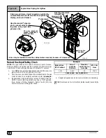
Manual shut- off
valve
Use elbows and 3
²²²²
pipe nip-
ple to connect valve to pip-
ing when using right side
gas pipe entry.
* Union may be installed inside the cabinet when necessary because of clearances.
Figure 29
Typical Gas Piping for Upflow
Drip Leg and Union, Union* should be outside the
cabinet. Manual shut--off valve MUST be upstream of
dripleg, union, and furnace.
LP Low pressure
switch. Optional on
some models.
Gas Pipe Grommet
(Single Pipe)
3
²²²²
pipe nipple
25--23--84
On some
models
25--24--22
Natural Gas Input Rating Check
NOTE:
The gas meter can be used to measure input to furnace.
Rating is based on a natural gas BTU content of 1,000 BTU’s per
cubic meter. Check with gas supplier for actual BTU content.
1. Turn
OFF
gas supply to all appliances and start furnace. Use
jumper wire on R to W1 and W2 for Hi fire.
2. Time how many seconds it takes the smallest dial on the gas
meter to make one complete revolution. Refer to
Example
.
3. Repeat steps 1 and 2 with jumper wire on R to W2 for low fire.
NOTE: Fourth (4th) dip switch must be in “ON” position.
(See Furnace Wiring Diagram). Return fourth (4th) dip
switch to previous setting after check.
Example
Natural Gas
BTU Content
No. of
Seconds
Per Hour
Time Per
Cubic Foot in
Seconds
BTU Per
Hour
1,000
3,600
48
75,000
1,000 x 3,600
¸
48 = 75,000 BTUH
4. Relight all appliances and ensure all pilots are operating.
NOTE:
If meter uses a 2 cubic foot dial, divide results (seconds) by
two.
Summary of Contents for 9MPT050F12A
Page 46: ...46 440 01 2020 01...


