


13
440 01 2020 01
AI
R
FLO
W
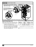
Figure 8
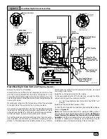
Upflow Installations Top Vent
Street Elbow
1
/
2
²²²²
CPVC
(Loose parts bag)
Casing Grommet
Black Rubber
5
/
8
²²²²
ID
(Loose parts bag)
Drain Tee
Drain Connector Black PVC
3
/
4
²²²²
PVC X
1
/
2
²²²²
CPVC
(Loose parts bag)
Drain Line Vent Tee
3
/
4
²²²²
PVC or
1
/
2
²²²²
CPVC (Field supplied)
1
/
2
²²²²
ID Drain
Hose & Clamps
5
/
8
²²²²
ID Hose & Clamps
3
/
16
²²²²
ID Rubber Tube
Coupling & Clamps
(Optional)
INLET
EXHAUS
T
25--24--42
Single Pressure Switch
Dual Pressure Switch Detail
Drain Tube (& Clamps) Black Rubber
5
/
8
²²²²
ID,
Cut length to fit (Loose parts bag)
On Some Models
ONLY
Yellow or black Plastic
Caps (2)
Vent Drain
& Clamps
Upflow Installations Top Vent
(See Figure 8)
Remove plug from the side of the furnace casing where Drain Tube
will exit.
Install casing grommet (black rubber
5
/
8
²
ID grommet -- in loose
parts bag)
Install the
1
/
2
²
CPVC street elbow on discharge of Trap
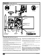
Install the black PVC tube connector (
3
/
4
²
PVC x
1
/
2
²
CPVC from
loose parts bag) as shown in the illustration above.
Cut the black Drain Tube (
5
/
8
²
ID -- in loose parts bag) to length to
fit between Trap and tube connector through grommet.
Clamp both ends of the Drain Tube using clamps provided.
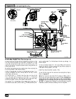
Glue the CPVC street elbow to the Trap using appropriate cleaner
and solvent cement.
Connect the Tee trap and the main drain line exiting the casing as
shown
Figure 17
.
Note:
It is recommended that all PVC piping and fitting connec-
tions be fit up and inspected before final cementing.
Trap must be
primed before operation.
Verify all condensate drain connec-
tions are securely clamped. A coupling and clamps (in loose part
bag) may be installed as shown for future servicing of the vent sys-
tem.
Summary of Contents for 9MPT050F12A
Page 46: ...46 440 01 2020 01...