background image

JOHNSON CONTROLS

4

FORM 150.68-EG1 (0212)

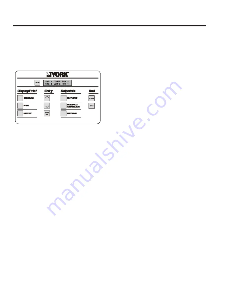
Microcomputer Control Center

The control panel includes:

•   A Liquid Crystal Display (two display lines of twenty 

characters per line) with Light Emitting Diode 
backlighting for easy viewing

•   A Colour coded 12-button keypad

•   Customer terminal blocks for control inputs and liquid 

fl ow switch.

The microprocessor control includes:

•   Automatic control of compressor start/stop, 

anticoincidence and anti-recycle timers, pump and 
unit alarm contacts. Automatic reset to normal unit 
operation after power failure.

•   Remote water temperature setpoint reset via analog 

input or a pulse width modulated (PWM) input signal 
or up to two steps of demand (load) limiting.

•   Software is loaded into the microprocessor controller 

via a SD card, with programmed setpoints retained in 
a lithium battery backed real time clock (RTC) memory.

•   Forty character liquid crystal display, with description 

available in fi ve languages (English, French, German, 
Spanish or Italian)

Programmable setpoints:

•   Chilled liquid temperature setpoint and range
•   Hot liquid temperature setpoint and range
•   Remote reset temperature range
•   Set daily schedule/holiday for start/stop
•   Manual override for servicing
•   Low ambient cutout
•   High ambient cutout (heating only - fi xed)
•   Low liquid temperature cutout
•   Low suction pressure cutout
•   High discharge pressure cutout
•   Anti-recycle timer (compressor start cycle time)
•   Anti-coincident timer (delay compressor starts)

Displayed Data:

•   Leaving liquid temperature 
•   Air coil defrost temperatures
•   Low leaving liquid temperature cutout setting
•   Low ambient temperature cutout setting
•   Ambient air temperature
•   Metric or Imperial data
•   Discharge and suction pressure cutout settings
•   System discharge and suction pressures
•   Anti-recycle timer status for each system
•   Anti-coincident system start timer condition
•   Compressor run status
•   No load condition
•   Day, date and time
•   Daily start/stop times
•   Holiday status
•   Automatic or manual system lead/lag control
•   Lead system defi nition
•   Compressor starts & operating hours (each 

compressor)

•   Status of evaporator heater and fan operation
•   Run permissive status
•   Number of compressors running
•   Mode solenoid valve status
•   Load & unload timer status
•   Liquid pump status

System Safeties:

•   Cause individual compressors to perform auto shut 

down and require manual reset in the event of 3 trips 
in a 90-minute time period

•   High discharge pressure
•   Low suction pressure
•   High-pressure switches
•   Motor protector

Unit Safeties:

They are automatic reset and cause compressor to shut 
down

•   Low leaving chilled liquid temperature
•   Under voltage
•   Loss of liquid fl ow (through fl ow switch)

For each system a common alarm contact for:

•   Low leaving chilled liquid temperature
•   Low voltage
•   Low battery
•   High discharge pressure (per system)
•   Low suction pressure (per system)
•   Compressor motor protection

Summary of Contents for YLPA

Page 1: ...ling Capacities 115 Tons to 170 Tons Cooling Capacities 400 kW to 600 kW Heating Capacities 1390 MBH to 2040 MBH Heating Capacities 400 kW to 600 kW 60Hz HFC 410A Model YLPA Air to Liquid Reversible S...

Page 2: ...5 6 7 8 9 10 11 12 13 14 15 BASE PRODUCT TYPE NOMINAL CAPACITY UNIT DESIGNATION REFRIGERANT VOLTAGE STARTER DESIGN DEVELOPMENT LEVEL Y York kW S Standard Unit E R 410A 4 0 X 380 3 60 B Design Series...

Page 3: ...core filter drier a sight glass with moisture indicator a cooling mode thermal expansion valve and a heat pump mode thermal expansion valve Suction lines shall be covered with closed cell insulation R...

Page 4: ...out High discharge pressure cutout Anti recycle timer compressor start cycle time Anti coincident timer delay compressor starts Displayed Data Leaving liquid temperature Air coil defrost temperatures...

Page 5: ...d mounted 2 SPRING ISOLATORS Restrained Spring Flex Mountings incorporating a rugged welded steel housing with vertical and horizontal limit stops Field mounted FLANGE KIT Provides contractor with the...

Page 6: ...es the direction of the refrigerant flow and the function of the heat exchanger to heating mode and the accumulator and enters the compressor where pressure and superheat are increased High pressure s...

Page 7: ...s 4 Compressors 8 Fans WEIGHTS AND WEIGHT DISTRIBUTION The weights and weight distribution are given below Model Shipping Operating R1 R2 R3 R4 L1 L2 L3 L4 0115SE 9811 10472 1864 1026 1414 2178 1822 2...

Page 8: ...ion On rooftop locations choose a place with adequate structural strength to safely support the entire operating weight of the unit and service personnel The unit can be mounted on a concrete slab sim...

Page 9: ...FORM 150 68 EG1 0212 9 JOHNSON CONTROLS A1 A B C D E A1 C C D D E A B C D A1 A4 A A B B A2 A3 A5 A B C D E E...

Page 10: ...changer s should be readily demountable to enable cleaning prior to operation and to facilitate visual inspection of the exchanger nozzles Each heat exchanger must be protected by a strainer preferabl...

Page 11: ...must meet the requirements detailed in the table below Water quality should be inspected before unit installation and regularly during unit operation The water quality must meet the limits above If pa...

Page 12: ...ay be wired into the unit This device should be rated at 20 amps 115V AC 15 The device should be wired into terminals L and 5 in the power panel after removing the factory fitted link CONTROL WIRING V...

Page 13: ...ction against loss of liquid flow Remote Start Stop Connect a remote switch to terminals 13 and 51 to provide remote start stop control if required Remote Mode Selection Remote mode selection can be a...

Page 14: ...13 15 13 20 13 21 13 50 13 51 A A STATUS SYSTEM STATUS SYSTEM 1 ALARM STAT 2 ALARM STAT P START CONTA ODE INDICATIO VERY OPTION O E START STOP FLOW SWITCH D INHIBIT N OPTION ONLY D FOR HEATING AGE LOA...

Page 15: ...0212 15 JOHNSON CONTROLS Water Pressure Drop Refrigerant to Water Heat Exchanger Pressure Drop Graph Pressure Drop ft H 2 O 100 Flow Rate gpm 200 300 600 400 1000 800 3 5 10 15 20 30 40 50 60 80 0170S...

Page 16: ...5 123 2 11 7 129 3 129 5 10 8 145 14 8 180 7 133 2 14 4 175 9 139 5 13 5 171 0 146 4 12 6 165 9 153 8 11 7 160 7 161 6 10 8 170 14 2 205 9 158 5 13 8 200 6 166 1 12 9 195 0 174 4 12 0 189 2 183 3 11 1...

Page 17: ...0 0 15 6 25 0 34 7 20 5 55 0 17 4 25 0 17 1 Displ Ambient F TONS COMP KW EER LOAD EER 100 0 146 3 157 3 95 0 10 1 100 0 10 1 80 0 126 6 112 2 86 9 11 8 75 0 13 1 60 0 100 0 73 6 76 0 13 8 50 0 15 8 40...

Page 18: ...73 7 206 7 3 4 115 1389 3 142 2 2 9 1474 9 142 8 3 0 1545 7 143 1 3 2 1616 4 143 3 3 3 145 1730 7 175 9 2 9 1837 3 176 5 3 0 1925 4 176 9 3 2 2013 6 177 2 3 3 170 2036 9 211 1 2 8 2162 4 211 9 3 0 226...

Page 19: ...5V 3 60Hz nominal 6 to 15 0170SE 0145SE 0115SE 95 to 131 YLPA 39 to 59 6 to 15 Cooling Mode 32 to 115 1 0115SE 0145SE 0170SE Number of refrigerant circuits Refrigerant Charge 1 System 1 System 2 lb 13...

Page 20: ...ressor RLA each compressor A 54 5 54 5 54 5 Compressor LRA each compressor A 310 310 310 Compressor Heater Supply V Hz 115 1 60 115 1 60 115 1 60 Compressor Heater Load W 600 750 900 Number of Fans Sy...

Page 21: ...6 1 1 5 4 7 Dimensions 1 Distance between anti vibration mounts 2 Power cable entry via gland plate 3 Control cable entry 4 Water inlet connection to heat exchanger 5 Water outlet connection to heat e...

Page 22: ...7 1 2 3 Dimensions continued 1 Distance between anti vibration mounts 2 Power cable entry via gland plate 3 Control cable entry 4 Water inlet connection to heat exchanger 5 Water outlet connection to...

Page 23: ...6 1 1 5 4 7 1 2 3 1 Distance between anti vibration mounts 2 Power cable entry via gland plate 3 Control cable entry 4 Water inlet connection to heat exchanger 5 Water outlet connection to heat excha...

Page 24: ...FORM 150 68 EG1 0212 Subject to change without notice Revision 0 ALL RIGHTS RESERVED www johnsoncontrols com...

Reviews: