


FORM 150.68-EG1 (0212)
11
JOHNSON CONTROLS
PIPEWORK ARRANGEMENT
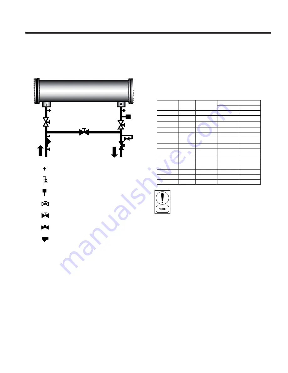
The following are suggested pipework arrangements for
single unit installations. For multiple unit installations,
each unit should be piped as shown. These are
recommendations of the Building Services Research
Association.
Isolating Valve – Normally Closed
Flow Regulating Valve
Strainer
Pressure Tapping
Air vent
Flow Switch
Isolating Valve – Normally Open
CONNECTION TYPES AND SIZES
Standard pipework connections are of the Victaulic groove
type.
For connection sizes relevant to individual models refer
to the physical data tables in this manual.
WATER TREATMENT
The unit performance given in the Design Guide is based
on a fouling factor of 0.0001 ft²hr°F/Btu. Dirt, scale,
grease and certain types of water treatment will adversely
affect the heat exchanger surfaces and therefore unit
performance. Foreign matter in the water system(s) can
increase the pressure drop, reducing the fl ow rate and
causing potential damage.
Aerated, brackish or salt water is not recommended for
use in the water systems. JCI recommends that a water
treatment specialist be consulted to determine whether
the proposed water composition will not affect the heat
exchanger materials of carbon steel and copper. The pH
value of the water fl owing through the unit must be kept
between 7 and 8.5.
WATER QUALITY REQUIREMENTS
The water used in the unit liquid system must meet the
requirements detailed in the table below:
Water quality should be inspected before unit
installation and regularly during unit operation.
The water quality must meet the limits above. If
parameters are not within limits, the heat
exchanger may leak or have problems within
scale formation.These problems may result in
the unit not operating normally, excessive heat
exchanger pressure drops and reduced nominal
capacities.
REFRIGERANT RELIEF VALVE PIPING
The heat exchanger is protected against internal refrigerant
overpressure by refrigerant relief valves. A pressure relief
valve is mounted on each of the main refrigerant lines
connecting the evaporator to the compressors. For indoor
installations, pressure relief valves should be piped to the
exterior of the building.
The size of any pipework attached to a relief valve must
be of suffi cient diameter so as not to cause resistance to
the operation of the valve. The internal diameter depends
on the length of pipe required and must be in accordance
with local regulations.
If relief pipework is common to more than one valve its
cross sectional area must be at least the total required by
each valve. Valve types should not be mixed on a common
pipe. Precautions should be taken to ensure that the exit
of relief valves/vent pipe remain clear of obstructions at
all times.
Allowable
Value
Corrosion
Fouling
pH (25°C)
pH
7.0 to 8.5
■
SO
4
ppm
<100
■
HCO
3
/SO
4
ppm
>1.0
■
Cl
ppm
<50
■
PO
4
ppm
<2.0
■
NH
3
ppm
<0.5
■
Free Cl
ppm
<0.5
■
Fe+++
ppm
<0.5
■
Mn++
ppm
<0.05
■
CO²
ppm
<10
■
H²S
ppm
<50
■
Temp
°C
<65
■
■
O content
ppm
<0.1
■
Hardness
dH
4.8 to 8.5
■
Item
Unit
Potential Problem


