


App-12
IM WT310E-01EN
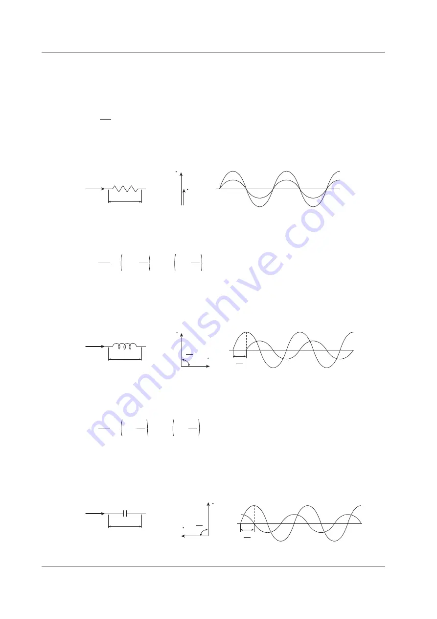
AC RLC Circuits
Resistance
The current i when an AC voltage whose instantaneous value u = Umsinωt is applied to load
resistance R [Ω] is expressed by the equation below. I
m
denotes the maximum current.
i =
U
m
R
sin
ω
t = I
m
sin
ω
t
Expressed using rms values, the equation is I = U/R.
There is no phase difference between the current flowing through a resistive circuit and the voltage.
R
I
U
U
I
i
u
Inductance
The current i when an AC voltage whose instantaneous value u = Umsinωt is applied to a coil load of
inductance L [H] is expressed by the equation below.
i =
U
m
X
L
sin ωt –
sin ωt –
π
2
= I
m
π
2
Expressed using rms values, the equation is I = U/X
L
. X
L
is called inductive reactance and is defined
as X
L
= ωL. The unit of inductive reactance is Ω.
Inductance works to counter current changes (increase or decrease), and causes the current to lag the
voltage.
L
I
U
U
I
π
2
i
u
π
2
Capacitance
The current i when an AC voltage whose instantaneous value u = Umsinωt is applied to capacitance C
[F] is expressed by the equation below.
i =
U
m
X
C
sin ωt +
sin ωt +
π
2
= I
m
π
2
Expressed using rms values, the equation is I = U/X
C
. X
C
is called capacitive reactance and is defined
as X
C
= 1/ωC. The unit of capacitive reactance is Ω.
When the polarity of the voltage changes, the largest charging current with the same polarity as the
voltage flows through the capacitor. When the voltage decreases, discharge current with the opposite
polarity of the voltage flows. Thus, the current phase leads the voltage.
C
I
U
U
I
π
2
i
u
π
2
Appendix 2 Power Basics (Power, harmonics, and AC RLC circuits)


