background image

6-22

IM 11Y01B01-01E-A    6th Edition :Feb 13, 2013-00

<6. BASIC OPERATION>

6.4 Reference Peak Lock with 2

nd

 Absorption Gas

In some measurement circumstances, instead of using the measurement gas (i.e. NH

3

) absorption peak to lock 

the laser wavelength tuning range, the analyzer uses an a H

2

O absorption peak near the NH

3

 absorption peak 

as the reference. This is because in the typical application process, NH

3

 concentration is normally zero or very 

low such that its absorption peak is not large enough for wavelength lock function. Moisture levels, however, 
are typically always high (about 10%) and therefore provide a large enough absorption peak for the wavelength 
locking function. Other applications using this same approach may include CO/CO

2

 or in some combustion 

applications, measure CO and lock onto an adjacent H

2

O peak.

There are two wavelength regions that need to be mathematically manipulated for an absorption spectrum: 
reference peak region and concentration prediction region. In the reference peak region, the H

2

O peak position is 

calculated for the laser wavelength lock. In the concentration prediction region, area integration is performed for 

NH

3

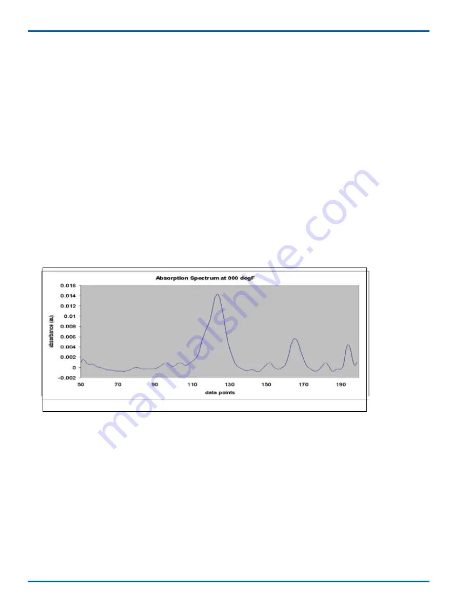
 concentration prediction. For example, the following spectrum is captured from a furnance test with a NH

3


analyzer. The reference peak region is at 150~180, and the measurement gas concentration prediction region is 
at 100~140.

For Off-Line Zero Calibration, make sure to purge Nitrogen (or dry Instrument Air) everywhere through the 
optical path so that there is no NH

3

 or H

2

O absorption in the spectra.

 For span calibration it is best to leave 

the laser temperature control as it is (there will be peak center out of range fault). Factory software access can 
further allow a change of the reference peak position set point to 124.5 (NH

3

 peak locking in the example shown 

below), or use manual laser temperature control mode.  

Figure 52 - Typical Process Gas Spectra with NH

3

 and H

2

O present

TDLS200 TDL Analyzer Instruction Manual V2.1 

Page 72 of 131


- 72 - 

4.5  Reference Peak Lock with 2

nd

 Absorption gas

In some measurement circumstances, instead of using the measurement gas (i.e. NH3) absorption 

peak to lock the laser wavelength tuning range, the analyzer uses an adjacent (i.e. H2O) 

absorption peak near the measured absorption peak as the reference. This is used when the 

measured gas concentration is normally zero or very low such that its absorption peak is not large 

enough for the wavelength locking function. The adjacent absorption peak level, however, is 

typically always high  and therefore provides a large enough absorption peak for the wavelength 

locking function. 

For the following explanation of “Reference Peak Lock” we will use NH3 as the “Measured Gas” 

and H2O as the “Reference Gas”.  The TDLS is measuring NH3 but is using an adjacent H2O 

absorption peak to maintain laser wavelength control. 

There are two wavelength regions that need to be mathematically manipulated for an absorption 

spectrum: reference peak region and concentration prediction region. In the reference peak region, 

the adjacent (i.e. H2O) peak position is calculated for the laser wavelength lock. In the 

concentration prediction region, area integration is performed for measured gas (i.e. NH3) 

concentration prediction. For example, the following spectrum is captured from a  test with an NH3 

analyzer. The reference peak region is at 150~180, and the measurement gas concentration 

prediction region is at 100~140. 

For Off-Line Zero Calibration, make sure to purge Nitrogen (or dry Instrument Air) 

everywhere through the optical path so that there is no measured gas or reference peak gas 

(i.e. NH3 or H2O) absorption in the spectra. 

For span calibration it is best to leave the laser 

temperature control as it is (there will be peak center out of range fault). Factory software access 

can further allow a change of the reference peak position set point to 124.5 (NH3 peak locking), or 

use manual laser temperature control mode.

Below: Typical Process Gas Spectra with NH3 and H2O present 

NH

3

H

2

O

Summary of Contents for TDLS200

Page 1: ...able Diode Laser Spectroscopy Analyzer IM 11Y01B01 01E A 6th Edition Yokogawa Corporation of America 2 Dart Road Newnan Georgia U S A 30265 Tel 1 800 888 6400 Fax 1 770 254 0928 Yokogawa Corporation of America IM 11Y01B01 01E A ...

Page 2: ...t unchanged on any change of specification construction or parts when the change does not affect the functions or performance of the product If the product is not used in a manner specified in this manual the safety of this product may be impaired Yokogawa is not responsible for damage to the instrument poor performance of the instrument or losses resulting from such if the problems are caused by ...

Page 3: ...aired If any protection or safety circuit is required for the system controlled by the product or for the product itself prepare it separately Be sure to use the spare parts approved by Yokogawa Electric Corporation hereafter simply referred to as YOKOGAWA when replacing parts or consumables Modification of the product is strictly prohibited The following safety symbols are used on the product as ...

Page 4: ...roducts and parts are guaranteed free from defects in workmanship and material under normal use and service for a period of typically 12 months from the date of shipment from the manufacturer Individual sales organizations can deviate from the typical warranty period and the conditions of sale relating to the origi nal purchase order should be consulted Damage caused by wear and tear inadequate ma...

Page 5: ... indicates that the operator must refer to the instructions in this manual in order to prevent the instrument hardware or software from being damaged or a system failure from occurring CAUTION This symbol gives information essential for understanding the operations and functions Note This symbol indicates information that complements the present topic This symbol indicates Protective Ground Termin...

Page 6: ... Process Interface 5 6 5 7 Typical Purge Gas Configuration In Situ 5 7 5 8 Typical Purge Gas Configuration Extractive trace ppm H2 O system 5 7 5 9 Dimensional Drawings 5 8 5 10 Wiring Drawings 5 14 5 11 Hazardous Area Systems 5 19 5 11 1 Purging Analyzer for Hazardous Areas with On Line Validation 5 20 5 11 2 Purging Analyzer for Hazardous Areas without On Line Validation 5 20 5 11 3 Purging Anal...

Page 7: ...tware Guide 6 38 7 Routine Maintenance 7 1 7 1 Maintaining Good Transmission 7 1 7 2 Alignment 7 4 8 Validation and Calibration 8 1 8 1 Off Line manual Automatic Checking and Off Line Calibration 8 2 8 2 Off Line Calibration for Reference Peak Lacking Application 8 13 8 3 On Line Validation 8 14 8 4 On Line Validation Overview 8 14 8 5 Performing manual On Line Validation 8 18 8 6 Performing Autom...

Page 8: ...S or URD then take 24 VDC to analyzer 3 2 Connect the Launch to Detect interconnect cable supplied with analyzer according to the supplied wiring detail TB7 on the Launch and TB 13 on the Detect Unit 3 3 Connect any analog I O signals to the analog I O Board Outputs land on TB8 and Inputs land on TB9 3 4 Connect any other equipment such as URD Ethernet solenoid valves digital I O etc 3 5 Check ter...

Page 9: ...pment has been exposed the lines should be a red color and thickness here see example photo of FLXA21 IM below If the analyzer displays a Warning Validation Required this indicates there is no target gas ab sorption peak found at start up Introduce some measured gas into the optical path and re start or perform a validation with target gas This will ensure that the analyzer is correctly tuned to t...

Page 10: ...that may be used to verify operation status diagnostics and other trouble shooting 9 10 Go to the Trends screen and review plot several of the listed parameters to check analyzer performance over a period of time 9 11 Non Process Parameters If the application use gas containing the target gas e g Oxygen measurement with Instrument Air Purge then the Non Process parameters should be configured as d...

Page 11: ...ote Interface Unit not required for normal operation Hazardous Area purge systems Other options may also be added 2 1 Functional Description Tunable Diode Laser Spectroscopy or TDLS measurements are based on absorption spectroscopy The TDLS200 Analyzer is a TDLS system and operates by measuring the amount of laser light that is absorbed lost as it travels through the gas being measured In the simp...

Page 12: ...ignal is used to quantify the light absorbed by the analyte Figure 3 Make sure the model number on the nameplate of the instrument agrees with your order The nameplate will also contain the serial number and any relevant certification marks Be sure to apply correct power to the unit as detailed on the nameplate For products used within the European Community or other countries requiring the CE mar...

Page 13: ... the European Community or other ries requiring the CE mark and or ATEX classification the ing labels are attached as appropriate For Zone 2 CAT 3 ATEX use the following labels will be attached as appropriate For YR 200 Remote Interface Unit RIU Zone 2 CAT 3 ATEX use the following labels will be attached as appropriate ...

Page 14: ...d Purge Control Unit must be sued with the TDLS Analyzer that is capable providing the requirements listed on label certificate and that either provides a suitable exhaust through a particle barrier of to a safe area When installed there shall be a minimum of two pressure regulators in the air nitrogen supply line The analyzer incorporates a variety of materials in its construction and they should...

Page 15: ...such that maintenance work must be carried out by trained personnel Trained personnel are considered as below Engineers familiar with the safety approaches of process analytical instrumentation and or general automation technology and who have read and understood the content of this User Guide Trained start up commissioning analyzer technicians who have read and understood the content of this Inst...

Page 16: ... card result files spectra capture configuration data etc Capture rate is configurable typical capacity for results and spectra is 14 days 2 3 or 4 150 ANSI RF or adaptors for DN50 PN16 and DN80 PN16 2 150 Alignment flange 4 5kg 10lbs 3 150 Alignment flange 9 5kg 15lbs 4 150 Alignment flange 9 1kg 20lbs 3 1 IM 11Y01B01 01E A 6th Edition Feb 13 2013 00 3 GENERAL SPECIFICATIONS 3 General Specificati...

Page 17: ...pecified and designed from the beginning to meet all SIL specifications Basic System Configuration The TruePeak can be installed in a number of ways depending on process requirements The most typical installation types are shown below however other installation methods are possible please contact Yokogawa with your application details Cross Stack Pipe Configuration Measures directly across process...

Page 18: ...losure with powder coated steel frame Heat tracing and insulation for flow cells and sample handling 316SS and or Monel A400 wetted parts other on request Sample handling and conditioning systems to suit applications Stream switching manual or automatic controlled by analyzer Note Custom configuration available to suit customer requirements Display and Software Functions TruePeak Software has mult...

Page 19: ... Hydrogen Sulfide H2 S up to 0 50 D1 Carbon dioxide CO2 High Range 0 1 0 5 D5 Carbon dioxide CO2 Extend Range 0 5 0 50 H1 Water moisture H2 O min 0 30ppm Cl2 background H2 Water moisture H2 O ppm non hydrocarbon background H3 Water moisture H2 O ppm Hydrocarbon background H4 High moisture H2 O level min 0 5 K1 Special Applications Laser Interface N None Blind Controller 1 Integral Mini Display 2 I...

Page 20: ...ged O Ring Alignment Flanged Metal Bellows Seal Alignment Flow Cell Isolation Flanges By Pass Piping Custom designs for specific applications Detect Unit Detect Electronics Housing Detector Assembly The Launch Unit and Detect Unit are connected to each other via a Tray Rated 4 pair shielded twisted pair cable The Launch Unit requires a single 24VDC power supply by customer or via optional Power Su...

Page 21: ...chamber allows Zero Gas or Span gas to flow through the measuring path for on line validation Laser Housing and Laser Module Laser diode and collimating lens assembly Laser module designed to be field replaceable and purged to prevent ambient air ingress Housed in a stainless steel body with O rings seals attached to the main electronics housing Laser Assembly Main Electronic Housing Check Gas Flo...

Page 22: ... has a cutout measuring approx 5 W x 4 H 130mm x 100mm A clear laminated safety glass window is mounted to the inside of the door with stainless steel fasteners and a weather tight gasket This allows for external viewing of the actual display without opening the door The right hand side of the door accommodates a keypad 30 keys stainless steel which is also operated externally without opening the ...

Page 23: ...sures The Back Plane has circuitry such that it can monitor for a return voltage The return voltage comes from remote Volt Free Contacts VFCs at the customer DCS or other control system The circuits include suitable protection against inadvertent shorting grounding of the supply 24VDC or the application of excess power to the monitoring circuit There are three sets of remote contact monitoring cir...

Page 24: ...outing functions for both power and signals I O for Detect Unit is routed through the Back Plane from one set of pluggable field terminals located lower left hand of Back Plane to the appropriate destination Terminals are provided for Analog DC power x3 Raw Detector Signal differential voltage x2 Detect Unit Temperature differential voltage x2 Analog I O Board outputs the analyzer results and read...

Page 25: ...splay Analog I O Board TB8 Analog Outputs three 4 20mA isolated TB9 Analog Inputs two 4 20mA powered or loop powered Optional Feed through Board URD only TB10 Ethernet to remote Analyzer via Interconnect Cable TB11 to remote Analyzer via Interconnect Cable TB12 Local Connections for RIU or URD Field I O 4 3 Laser Assembly The laser assembly contains Laser Diode Collimating Lens Module Body Window ...

Page 26: ...nlet and outlet ports for the nitrogen purge gas or calibration check gas as appropriate The Check gas flow cell is used for performing on line validations or Dynamic Spiking while the analyzer is mounted on the Process This feature allows for the analyzer to be validated without removing it from the Process location By introducing a gas of known target gas concentration at a given temperature and...

Page 27: ...vert detector photocurrent into voltage and send it to be digitized LEDs are incorporated to provide simple diagnostic of available power The board has a temperature sensing chip circuit that monitors the ambient temperature inside the detect electronics enclosure The sensor is located on the top edge of the detect board to ensure the maximum temperature reading is monitored The board is medium si...

Page 28: ...pprox 4 H x 6 W printed circuit board that mounts inside the enclosure The field terminations are located along the lower edge of the board via pluggable terminal block All components and devices on the board are designed for extended temperature and low drift operation 2 3 7 Process Interface An appropriate Process Interface is selected to suit the process stack installation The analyzer is detac...

Page 29: ...luminum Foil Polyester tape 100 coverage with 18 AWG tinned copper wire drain Outer Jacket F R PVC Flame Retarding Polyvinyl Chloride Wall thickness 0 053 1 35 mm Typical 0 47 12 mm outside diameter Operating temperature 22 to 221ºF 30 to 105ºC Min Bend Radius 5 127 mm Applicable Standards NEC UL PLTC ITC CMG Flame Test UL1581 FT4 IEEE 1202 ICEA T 29 520 Suitability Indoor Outdoor Burial and Sunli...

Page 30: ...emote Interface Options A number of options are available for remote access to the analyzer Remote Interface Unit RIU model YR200 shown below allows remote analyzer control and data transfer from analyzer to RIU data can be transferred from RIU via USB memory stick or Compact Flash card Allows multi unit field communication via central user interface Not required for individual analyzer operation ...

Page 31: ...make the 10 100 Ethernet connection Figure 15 Connecting RUI to Analyzer s TDLS200 TDL Analyzer Instruction Manual V2 1 Page 32 of 131 32 The unit acts as a remote interface for the analyzer Should the physical location of the actual analyzer s be inconvenient for easy access then the RIU can be used It can be mounted up to 100m 330ft away from the analyzer s using the standard 10 BaseT twisted pa...

Page 32: ...Page 33 of 131 33 RIU Optional Ethernet Switch If there is more than one analyzer connected to the RIU then they are routed via an industrial Ethernet switch Up to four analyzers can be routed through one RIU switch The switch is powered by 24VDC from the back plane and includes several status LEDs Figure 11 RIU Ethernet Switch RIU Optional Feed through Board To facilitate the connection of more t...

Page 33: ...1 Division 2 Groups A D ATEX Zone 2 CAT 3 The block diagram below shows the sections of the analyzer that require nitrogen purging A Z Type purge control system is fitted the Main Electronics Housing and it includes a local indicator and pressure switch alarm contacts The purging should be carried in sequence typically as shown below Figure 17 Purging for Safe Areas Nitrogen or I A Purge Gas Laser...

Page 34: ...as temperature Lower gas temperatures generally lead to better measurements Process Gas Pressure It is recommended that the analyzer be installed at a location where pressure fluctuations are minimized Generally as a guide if the pressure of the gas at the point where the analyzer is to be installed is to vary by more than 0 05 Bar 0 725 psi then an Active input signal should be used for compensat...

Page 35: ... V2 1 Page 40 of 131 0 4 3 2 Position of Process Flanges for Launch and Detect Units Process flanges should be located on the process such that the Launch and Detect Units can be installed accessed removed in a safe and convenient manner The following criteria Check List should be met at a minimum Good Safe Engineering practices Local codes and regulations for such equipment installation Appropria...

Page 36: ...ion however it is the installer s responsibility to ensure appropriately rigid installation is provided for the analyzer Figure 25 Launch or Detect Unit Installation Dimensions TDLS200 TDL Analyzer Instruction Manual V2 1 Figure 21 Reinforcing Plate for Launch or Detect Unit Flanges 3 3 Process Flange Welding Alignment and Line Up The Launch and Detect units are provided with alignment mechanisms ...

Page 37: ...ch or Detect Unit Flanges 3 3 Process Flange Welding Alignment and Line Up The Launch and Detect units are provided with alignment mechanisms that allow for some m adjustment of the laser beam direction in both planes It is however recommended that the following angular tolerances be adhered to as closely as possible Figure 22 Angular Alignment Tolerances for Launch or Detect Unit Flanges PROCESS ...

Page 38: ...14 9 1 Vortex Tubes 14 10 Sub Component Documentation 15 10 1 Vortex Tube Installation and Maintenance 15 17 10 2 Installation and Maintenance for SA Control Valve 18 24 11 2 1 General Safety 19 11 2 2 Tech Details 19 11 2 3 Install and Commiss 20 22 11 2 4 Maintenance 23 24 10 3 Supplement Safety Information 25 10 3 1 Intended Use 25 WARNING This symbol indicates that an operator must refer to th...

Page 39: ... tubing to the purge gas supply The exact purge gas flow rate will be dependant upon the process conditions that exist at the flange connection and therefore the flow rate could be anywhere from 5lts min to 50lts min 10 SCFH to 100 SCFH Ensure the purge gas line is clean and dry prior to connecting to the flange to ensure any condensate or debris is not blown on to the windows at initial start up ...

Page 40: ...tion In Situ Please refer to project specific details the following is a typical standard in situ configuration 5 8 Typical Purge Gas Configuration Extractive trace ppm H2O system Please refer to project specific details the following is a typical standard enhanced flow cell configuration Figure 31 Figure 30 ...

Page 41: ...ION AND WIRING 5 8 IM 11Y01B01 01E A 6th Edition Feb 13 2013 00 5 9 Dimensional Drawings Figure 33 General Installation Clearance Requirements Typical Purge Large Aperture Optics LAO combustion O2 CO CH4 Figure 32 ...

Page 42: ... 5 INSTALLATION AND WIRING 5 9 IM 11Y01B01 01E A 6th Edition Feb 13 2013 00 Figure 34 Off Line Calibration Overview Figure 35 Launch and Detect unit Dimensions ...

Page 43: ... 5 INSTALLATION AND WIRING 5 10 IM 11Y01B01 01E A 6th Edition Feb 13 2013 00 Figure 36 Remote Interface Unit Figure 37 Universal remote Display URD ...

Page 44: ... 5 INSTALLATION AND WIRING 5 11 IM 11Y01B01 01E A 6th Edition Feb 13 2013 00 Figure 38 Universal Power Supply UPS Figure 39 Alignment Bellows Other flange sizes available to meet application needs ...

Page 45: ... 5 INSTALLATION AND WIRING 5 12 IM 11Y01B01 01E A 6th Edition Feb 13 2013 00 Figure 40 Large Apenture Other flange sizes available to meet application needs Figure 41 Isolation Flanges model IF200 ...

Page 46: ... 5 INSTALLATION AND WIRING 5 13 IM 11Y01B01 01E A 6th Edition Feb 13 2013 00 Figure 42 Insertion Tube Detail Figure 43 Off Line Calibration Gas and Purge Detail ...

Page 47: ...TALLATION AND WIRING 5 14 IM 11Y01B01 01E A 6th Edition Feb 13 2013 00 Figure 44 Utility Panel Tubing Detail Standard Single Auto validation Figure 45 Utility Panel Tubing Detail Standard Dual Auto validation ...

Page 48: ... 5 INSTALLATION AND WIRING 5 15 IM 11Y01B01 01E A 6th Edition Feb 13 2013 00 5 10 Wiring 5 10 1 Wiring of Launch for the US version Figure 46 ...

Page 49: ... Total induced voltage of 3Vrms A combination of these parameters will cause measurement error outside of the analyzer performance specification In practice these potential errors can be easily avoided by routing the 4 pair launch to detect cable away from electromagnetic interference sources that could exhibit these parameters Such sources might include power transformers electric motors electric...

Page 50: ...ATION AND WIRING 5 17 IM 11Y01B01 01E A 6th Edition Feb 13 2013 00 Launch and Detect Unit Wiring Standard GP Div2 non CE ATEX Launch Unit to Detect Terminations at TB 7 Detect Unit to Launch Terminations at TB 13 ...

Page 51: ...it Terminations CE ATEX GP Div2 all units SEE FOLLOWING NOTES Please NOTE that ALL analog output signals from TB 8 are POWERED BY THE ANALYER Outputs from TB 9 can be configured for POWERED inputs or LOOP POWERED external transmitter PLEASE CHECK CAREFULLY BEFORE APPLYING POWER TO THE ANALYZER ...

Page 52: ...al Specifications 5 3 Theory of Operation 6 3 1 Brief History of Reflux Samplers 6 3 2 Filter Section 6 3 3 Steam Supplement 6 3 3 Inlet Temperature Section 6 3 4 Heat Exchanger Section 6 7 3 5 Outlet Temperature Section 7 3 6 Self Acting Temperature Controller 7 3 7 Instrument Air for the Vortex Tube 7 3 8 Vortex Theory of Operation 7 4 Utility Requirements 8 4 1 Instrument Air 8 4 2 Low Pressure...

Page 53: ...ng on line validation 3 9 3 Purging Analyzer and Universal Power Supply and or URD for Hazardous Areas with On Line Validation Z Purged designed in accordance with NEC CSA Class 1 Division 2 Groups A D Certified ATEX Zone 2 CAT 3 Dual regulators must be used on the inlet The block diagram below shows the sections of the analyzer that require nitrogen purging when using in conjunction with either o...

Page 54: ...that require nitrogen purging when using in conjunction with either or the Universal Power Supply and Universal Remote Display A Z Type purge control system is fitted the Launch Unit and it includes a local indicator Bright Green rugged light and pressure switch alarm contacts open on loss of purge pressure Figure 29 Purge Flow Diagram when using on line validation Main Electronic Housing Purge Sy...

Page 55: ...losure register s a pressure of at least 0 20 inches H2 O 0 50 mbar above the reference atmospheric pressure a manually controlled dilution time cycle may then begin Typically a minimum dilution time cycle is specified to ensure that at least five times the volume of free space in the electronics enclosure is exchanged before power is manually applied to the electrical equipment The number of exch...

Page 56: ...lumes may be higher in some situations Refer to TDLS 200 ATEX Purge Warning Labels for Details NOTE Instrument Air and Nitrogen purge gases have different purge time requirement It is important to use clean dry purge gases to ensure the pressure switch contacts do not foul and cause subsequent operating issues i e non functionality of the Cyclops Utility Requirements Purge Protective Gas Supply Pr...

Page 57: ...esh Current Trend screen Min Max Minutes ADVANCED Password Protected Configure Process Path Length Current New Confirmation of Change Confirmation of Change Pressure Fixed Active Control similar to Fixed Current New 4 20 mA Backup Desired Range Center of Pressure control Confirmation of Change Confirmation of Change Confirmation of Change Temperature Fixed Active Input Active Ambient Active Peaks ...

Page 58: ...of range Board temperature out of range DO Warning delay Faults Laser temperature out of range Detector signal high Dectecor signal lost Measurement peak no response Peakcenteroutofrange 2ndgas threshold Walidation failure base concen trations DO fault delay User Alarm Conc Trans Val Cal High Low and limit DO use alarm delay System Serial Number Laser Serial Number Password Old Password New passwo...

Page 59: ...pan Calibration Manual Automatic Local Initiate Remote Initiate control channel Time Initiate frequency Settings conc opl temp pres Restore Old Calibration Factory Calibration Transmission Pres temp opi gas type conc Dark Current Peak Search Peak with Lower WL Opeak with Higher WL All Peaks Result Display Offline Validation Validation Gas 1 Validation Gas 2 Two Gas Validation similar to Gas 1 Manu...

Page 60: ...tus Data Transferring Transfer Success Transfer Failure Data Transfer Status Line 4 Information Yokogawa TDLS SN 76 1xxx 05 xx AO1 CONC xx xx ppm ppb mg m3 or mg Nm3 AO2 TRANS xx xx AO3 TEMP xx xxF C K 10 0 0 35 TEMP Act Con Fox xx F C K PRES Act Con Fix xx x PsiA BarA KPa torr atm OPL xx x in ft cm m Launch xx deg C Detect xx deg C Analyzer Name Analyzer Serial No Configured 4 20mA output for AO1...

Page 61: ...nter mA value form 0 20 Block will hold outputs at user selectable mA example shows 3 8mA until return to Main Screen but NOTE CHANNEL 2 ALWAYS TRACKS Track will allow outputs to continue to report concentration and transmission until return to Main Screen Hold will hold outputs at their current value until return to Main Screen NOTE CHANNEL 2 ALWAYS TRACKS BASIC MENU Configure allows setting of P...

Page 62: ...ent of the gas pressure value if using fixed pressure If the analyzer is using active pressure compensation live signal fed from pressure transducer or active ambient no changes are allowed Active pressure compensation settings are found in Advanced Menu IP ADDRESS displays the analyzer IP address SERIAL NO displays analyzer serial number VERSION software version number The spectra screen raw dete...

Page 63: ...C analyzer reading of gas concentration shown here as O2 or whatever Gas 1 is configured STDEV1 the standard deviation of 25 consecutive concentration readings for gas concentration 1 Gas2 analyzer reading of gas 2 concentration STDEV2 the standard deviation of 25 consecutive concentration readings for gas concentration 2 TRANS transmission of laser light through the process gas LTS analyzer laser...

Page 64: ...Example would be Instrument air purge when measuring Oxygen or CO line locking gas for combustion CO applications UNITS selection as defined below independently SYSTEM I O allows set up and assigning of analyzer Analog and Digital I O SYSTEM displays analyzer information serial number Fat date password software version launch detect unit temperatures etc allows setting of date time TCP IP VALVE CO...

Page 65: ... required If there is any process temperature variation then the results are typically affected according to the specific application ACTIVE INPUT is used when the highest degree of accuracy is required under variable process temperature conditions or when specified for the given application The range must match the 4 20mA input range and a back up value may be entered in case the input signal fai...

Page 66: ...e Block Track Hold modes and is typically assigned to Transmission WARNING MODE setting of mA output response during analyzer warnings Block Track Hold FAULT MODE setting of mA output response during analyzer warnings Block Track Hold FIELD LOOP CHECK allows specified 4 20mA output levels to check and distinguish between the three analog output connections select analog output channel 1 2 or 3 to ...

Page 67: ...INGS CONDITIONS ARE IMPORTANT SETTINGS DETECTOR SIGNAL LOW lower raw detector signal limit TRANSMISSION LOW lower limit of transmission Note when transmission falls below this value the automatic peak tuning function is disabled This is to prevent excessive noise caused by low transmission interfering with correct peak tuning SPECTRUM NOISE HIGH factory set do not adjust PROCESS PRESSURE OUT OF RA...

Page 68: ...k i e the measured absorption peak falls below the set threshold value consult factory for further details if attempting to implement Line Locking gas and or non process parameters To disable this Fault only under guidance from factory authorized personnel please enter a value of 1 PEAK CENTER OUT OF RANGE loss of peak center control VALIDATION FAILURE Allows the user to refine the most appropriat...

Page 69: ...EL 3 USER ALARMS Enables digital output alarm for concentration value High or Low Transmission High or Low or Validation Calibration the contact changes state during a validation or calibration DIGITAL INPUT STATUS CHECK The user can check the status of remote Digital Inputs ...

Page 70: ...ware Version VALVE CONTROL Typically used when the analyzer is configured with a flow cell in an offline application These values can also be used manually to introduce on line validation gases Valve configuration conflicts will be noted on screen if applicable VALVE 1 Manual On Off Toggle Time Sequence next valve and time seconds to next valve or Remote Control select D I channel for control capa...

Page 71: ...TS In manual mode allows adjustment of laser temperature ONLY ADJUST WITH FACTORY ASSISTANCE NOTE the analyzer will return to automatic mode if un touched for 30 minute LTSP LIMITS setting of guard limits for laser temperature set point ONLY ADJUST WITH FACTORY ASSISTANCE MAX CURRENT setting of center point for laser current ramp ONLY ADJUST WITH FACTORY ASSISTANCE FAST UP DATE this function can b...

Page 72: ...rge paths are correctly configured TRANSMISSION adjustment of transmission value DARK CURRENT DISABLED feature Factory use only PEAK SEARCH DISABLED feature that initiates a system scan of absorption peaks to validate current peak selection is correct Factory use only OFFLINE VALIDATIONS CHECK GAS 1 to 2 allows manual or automatic configuration up to 2 check gasses Two Gas Validation allows the us...

Page 73: ... is a of reading change or ABSOLUTE concentration level to trigger capture in addition the software will prompt for number of spectra to capture when a Warning or Fault occurs MANAUL selection will result in spectra capture only when requested by user CAUTION By setting a high spectrum capture rate i e a low number between up dates the memory can very quickly fill up and because the system uses a ...

Page 74: ...rget measured gas The most common application of this is to use Instrument Air 20 9 O2 as the purge gas for analyzers measuring Oxygen in the process Another common use of this feature is Line Locking whereby some target gas typically CO for CO CH4 combustion analyzers is locked into the validation cell at all times and therefore its absorption contribution must be accounted for The valve function...

Page 75: ...purge may exist in several section of the optical path including Inside the Launch unit body laser module section Inside the Launch unit body online validation cell Inside the Launch unit alignment flange Inside the launch side process nozzle and valve Inside the Detect unit body Inside the Detect unit alignment flange Inside the Detect side process nozzle and valve It is important that these dime...

Page 76: ...e locking gas is being used such as CO for combustion CO CH4 applications NON PROCESS PATH LENGTH This is the optical path length between the laser and detector excluding the process path length The factory values entered include the analyzer internals and the alignment flanges The distance of process isolation valves and process nozzles on both Launch and Detect sides MUST be added to the existin...

Page 77: ...AULT Alarm when the peak height is lower than 0 001 au see absorption spectrum This value can be determined with assistance from the Yokogawa factory to suit the specific application This alarm function can be used to help detect the leakage or loss of line locking gas for example CO on combustion CO CH4 applications To disable this alarm simply enter 1 as the threshold value with the toggle in ei...

Page 78: ... set point to 124 5 NH3 peak locking in the example shown below or use manual laser temperature control mode Figure 52 Typical Process Gas Spectra with NH3 and H2 O present Page 72 of 131 72 absorption peak near the measured absorption peak as the reference This is used when the measured gas concentration is normally zero or very low such that its absorption peak is not large enough for the wavele...

Page 79: ...or reference gas i e NH3 and H2 O in the entire optical path Process OPL and Analyzer Purge required for an Off Line Zero Calibration of the analyzer Process Calibration OPL 20 ppm NH3 Analyzer Purge N2 In this Absorption Spectra view there is practically zero reference gas H2 O absorption peak in the approximate peak center position PCP 167 region There is approximate 20 ppm of measured gas NH3 a...

Page 80: ...6cm OPL ambient temperature and ambient pressure Page 74 of 131 74 On Line Process Conditions Analyzer Purged with Nitrogen Process OPL Measured and Reference gas NH3 and H2O Analyzer Purge N2 In this Absorption Spectra view the reference gas H2O absorption peak can be seen at approximate peak center position PCP 167 This absorption peak is from the reference gas contained in the process stream H2...

Page 81: ...ge H2 O absorption peak can be seen at approximate peak center position PCP 167 There is no NH3 absorption in the spectra Process OPL 20 ppm NH3 Zero H2 O Analyzer Purge Air typical 2 4 H2 O In this Absorption Spectra view the H2 O absorption analyzer air purge peak can be seen at approximate peak center position PCP 167 There is approximate 20 ppm NH3 absorption approx 120PCP in this spectra base...

Page 82: ... a long path installation the diverging beam power is spread out over a larger area and hence weaker this means that once installed on the long path the detector gain may require some manual adjustment increase typically please use the following procedure TDLS200 TDL Analyzer Instruction Manual V2 1 Page 76 of 131 76 4 6 Large Aperture Optics For in situ application typically large scale combustio...

Page 83: ... the maximum transmission can be found Place setscrews so that the alignment is secure With the detector aligned begin vertical adjustments of the launch unit using the studs for small fine adjustments to attain maximum transmission Once maximum transmission has been found in the vertical position adjust the horizontal plane for maximum transmission With maximum transmission found in the horizonta...

Page 84: ...tors with the following values All of them are W 5 tolerance metal film through hole resistors Resistor Bag for Analyzers With Diverging Beam Optics Resistance Ω 100 1k 1 5k 2 2k 3 3k 5 1k 7 5k 11k 16k 24k Quantity 1 2 2 2 2 2 2 2 2 2 Please record the factory gain resistors currently installed on the detector board R21 _____________ R22 _____________ R23 ____________ PROCEDURE 1 This procedure re...

Page 85: ... and R23 to the next smaller value available in the resistor bag and then go back to STEP 6 For example if the current R22 and R23 values are 11kΩ the new R22 and R23 values should be 7 5kΩ NOTE please access Active Alarm in the main user interface panel to check if Detector Signal High fault is active b If the raw detector signal is within requirement remove R22 and R23 and R21 if it was changed ...

Page 86: ...treme caution to prevent a short circuit on the board i e loose wires or touching adjacent components with pliers or tool used to install resistor Please keep the factory original gain resistors in the resistor bag as they will be used in the future for offline calibration or test The raw detector signal MAX MIN is proportional to R21 R22 R23 Usually R21 is maintained as factory value R22 and R23 ...

Page 87: ...l current monitoring so any externally applied voltage current may cause damage to the analyzer hence use voltage free contact only It can happen only when no auto calibration or validation is on going Direct control from DCS and or local remote switch s Contact signal valve on please keep remote contacts closed for at least 10seconds to ensure the analyzer reads registers the contacts at measurem...

Page 88: ...he gas temperature pressure and its bulk composition are defined absorption spectrum depends only on the absorption path length which is also fixed in the supplied analyzers These analyzers are factory calibrated and Therefore the H2 Oppm in Natural Gas analyzers DO NOT require actual field calibration by end users they can however be Validated Calibration procedure described in the standard TDLS2...

Page 89: ...s not visible to the eye within this absorption spectrum when 100 ppm as shown blue in absorption spectrum right 6 8 Introduction to Gas Temperature Predictions with High Temperature Oxygen Measurements For some high temperature oxygen measurements operating at the correct conditions the analyzer can predict the gas temperature as well as the oxygen concentration The TruePeak TDL analyzer scans a ...

Page 90: ...r oxygen levels are preferred contact Yokogawa Laser Analysis Division with application details 6 9 Controlling the Analyzer Remotely or Locally via external PC Laptop A number of methods are available to connect to the TDLS200 analyzer Direct Access with optional Keypad and Display Direct Access using VNC and an external computer Ethernet Remote Access using VNC via network external computer Remo...

Page 91: ...viewer exe file should be loaded on to the connecting PCs desktop ready for use when connecting with the analyzer From Control Panel Network Connections make sure Ethernet Local Area Connection is set to Enabled status Disable wireless and any other networking connections Connect crossover Ethernet cable from client system to Analyzer On the computer go to Control Panel Network Connections Local A...

Page 92: ...password for entering the VNC connection screen is 1234 see screen below that shows an example IP address of 10 0 2 14 for an analyzer Serial number XX 1214 XX etc DO NOT attempt to change of the Quick Options or any other settings on this menu If the analyzer connection cannot be established see error message below then check the PC IP settings connection wires Cat5 cable and IP address 6 9 2 Usi...

Page 93: ...h Edition Feb 13 2013 00 6 BASIC OPERATION 6 9 3 OPTIONAL Remote Interface Unit RIU The OPTIONAL RIU runs the Virtual Analyzer Controller VAC software described below 6 9 4 Virtual Analyzer Controller VAC Operating Software Map ...

Page 94: ...ections by name and or IP address After selecting Connect F2 you will be allowed to select the analyzer with description and IP address you wish to control remotely This will allow full analyzer control as if you were at the analyzer itself Please remember that when you have finished working on the analyzer via this RIU VAC software you must END SESSION to the analyzer by pressing the Control Back...

Page 95: ...ptions Configuration Menu Data Dump Options This sets the directories to receive data from analyzer and send data to on system running VAC software Source Directory This is the analyzer data file folder it should not be changed without factory consultation Target Directory This is the remote computer or RIU directory to receive data files File Masks These are the extensions of the files to be tran...

Page 96: ...nd when the RIU screen turns white the power can be switched off Note there is no watch dog in the RIU so un like the TDLS 200 it will not automatically re start after a period of time if power is not switched off ALWAYS END VNC SESSION TO ANALYZER WHEN DONE THIS WILL PREVENT THE ANALYZER AND OR RIU FROM HANGING DO NOT LEAVE THE RIU PERMANENTLY CONNECTED TO ANALYZER CONNECT ONLY WHEN IN USE ...

Page 97: ...s the dirty process gas to contact the windows and leave deposits Loss of window purge gas flow pressure which then allows the hot process gas to contact the window condense any liquids and leave deposits Over pressure of the process gas which allows the process gas to overcome the window purge gas and contaminate the window Contact on the window by an incompatible gas such as HF on the standard B...

Page 98: ...gure 33 Window Replacement 5 1 2 Replacing Windows If it has been determined that a window required replacement then the following should be performed Shut down the analyzer and remove power thus ensuring the laser if OFF Remove Launch or Detect as appropriate from the process interface by removing the one fixed hole fastener 5 32 Allen Wrench loosening the remaining three fasteners and then twist...

Page 99: ...e same specification as the window being removed Standard Windows are 0 25 Thick wedged BK 7 borosilicate crown glass mounted in stainless steel retaining ring The window holder assemblies can only be installed in one way by virtue of the mounting hole placement Ensure a new O Ring of same specification is installed at the same time Viton is the standard material however certain applications may r...

Page 100: ...ge Window Purge Port x2 Figure 34 Alignment Mechanism 7 2 Alignment 7 3 Data Reporting Storage and Retrieval The TDLS200 analyzer has been designed with extensive data reporting capabilities All data is available in the analyzer as a text file for import into a spreadsheet for analysis Data stored in the analyzer Results Every measurement the gas concentration transmission diagnostic data are stor...

Page 101: ...te On Line Automatic Initiated by Remote Contact Local User Interface Pre Set Timer URD Laptop VAC RIU User Interface Analyzer remains attached to process and also considered as a gas response check method Use integral on line check gas flow cell Automatic introduction of check gas requires appropriate hardware valves etc and implements automatic procedure from selected initiation method Validate ...

Page 102: ...ow cell enhanced flow cell or low volume flow cell then it is already capable of being validated calibrated in off line mode Before removing the units from the process ensure that the process gas and window purge gas are correctly isolated to prevent excessive pressure process or purge gas from being released or from over pressuring the analyzer AVOID SHOCK AND IMPACT TO THE ANALYZER PERMANENT LAS...

Page 103: ...removal process for the Launch unit and place it VERY CAREFULLY adjacent to the off line calibration cell 7 Check to see that there are three Allen Head screws in the top left top right and lower left positions and that they are backed out to clear the analyzer quick connect Attached the Detect unit to one end of the off line calibration cell Carefully slide the unit over the O Rings making sure t...

Page 104: ...mall misalignment of the system 6 see POOR alignment example right Carefully make small adjustments in the alignment of launch unit to minimize the slope at the start of the raw detector ramp Then Carefully make small adjustments in the alignment of detect unit to minimize the slope at the start of the raw detector ramp for good alignment see GOOD alignment example right 7 Ensure transmission leve...

Page 105: ...he detailed on screen instructions when check the analyzer zero and or checking the span 14 We do not recommend calibrating the Zero unless some core spare parts have been replaced such as laser module or FPGA board If the Zero reading appears incorrect then ensure all data results and spectra have been stored and send the files to Yokogawa Laser Analysis Division for further evaluation Apply zero...

Page 106: ... absorption peak indicating that the zero gas had not fully purged the optical path Perform the zero calibration again in either case or check with your local Yokogawa representative If there is reason to restore either zero calibration then please follow the on screen instructions When an acceptable zero has been established arrange the purge tubes as shown below and then follow the on screen ins...

Page 107: ...within the analyzer or as in the example below there is no second measured gas configured Note after entering the desired span gas value the following display will prompt you to press 9 to actually perform the calibration or escape to cancel Note the concentration that is being displayed and up dated in the lower box is the currently measured value before the calibration is performed After calibra...

Page 108: ...00 8 VALIDATION AND CALIBRATION If there is reason to restore either a Span calibration then please follow the on screen instructions For Automatic Off Line Calibrations used only on extractive applications please follow the on screen instructions ...

Page 109: ...8 9 IM 11Y01B01 01E A 6th Edition Feb 13 2013 00 8 VALIDATION AND CALIBRATION ...

Page 110: ...nto the Advanced Menu Calibrate Validate section Off Line Validations Choose Check gas 1 2 or two gas validation and select Manual Validation Following the on screen directions enter in the pressure temperature cell length concentration of the gas within the off line line check gas flow cell Press Enter to proceed ...

Page 111: ...Validations can also be automatically configured Refer to later section for details Local Initiate will start the automatic online validation sequence when selected It will use the existing Settings see below for details on Settings Remote Initiate will enable disable monitoring of the selected Remote Initiate contacts on TB 2 within the Launch Unit When enabled the analyzer will detect the chosen...

Page 112: ...l be used whenever the auto validate is used so try to select a value that is representative of when the auto validate might take place day night etc Press ENT to proceed Check Gas Pressure specifies the pressure at which the gas within the offline line flow cell Valve Selection specifies which analyzer s solenoid valve driver is used for the check gas Check Gas Purge Time specifies how long the c...

Page 113: ...n Spectra view there is practical ly zero H2O absorption peak in the approximate peak center position PCP region There is approximate 20ppm NH3 approx PCP 120 absorption in this spectra based on 72 6cm OPL ambient temperature and ambient pressure Note other target gases such as CO CO2 HCN etc will also require only target gas absorption spectrum at the time of off line calibration This is the typi...

Page 114: ... scans this region approximately 1 000 times per second while accumulating the spectra in memory The scanning i e wavelength adjustment is controlled by rapid adjustment of the electrical drive current on the diode itself 2 Operating and Maintenance Manual 1 Introduction 4 1 1 Features 4 2 General Specifications 5 3 Theory of Operation 6 3 1 Brief History of Reflux Samplers 6 3 2 Filter Section 6 ...

Page 115: ...gen present Raw Detect Signal No Oxygen present Raw Detect Signal Oxygen Present The TruePeak TDLS200 uses the raw detector signal to produce the actual absorption spectra see below note the vertical scale in Absorbance Units is different between the two spectra which is then used to calculate the peak area It is the peak area that is proportional to the oxygen concentration with given process par...

Page 116: ...ing spectra allow for a base line to be drawn below the absorption curve and subsequent true peak area calculation On Line Validation By knowing the above measurement principles it is possible to understand that the TDLS200 is capable of performing on line validations to verify analyzer measurement performance When the analyzer is initially calibrated off line using protocol certified gas standard...

Page 117: ...ly before and after validation Spectra 2 is the combination of process and validation gas so when the averaged 1 3 spectra is subtracted the peak area remaining is that of the validation gas at 4 OPL ambient temperature and pressure This area measured for validation gas should therefore match the expected value because all other parameters are known If the measured true peak area matches that of t...

Page 118: ... Flow Cell Inlet Max 3 psig TYP 2LTS min Analyzer Purge N2 Gas Inlet TYP 2LTS min NO NC C Via the user interface laptop PC and VNC Viewer or installed 6 5 Display and Keypad follow this sequence Enter into the Advanced Menu Calibrate Validate section Enter On Line Validations then Manual Validation Ensure the check gas is ready to start purging the integral on line check gas flow cell BUT DO NOT s...

Page 119: ...is cell is the same temperature as ambient Use a thermometer DVM with appropriate thermocouple attachment or radio to the control room for an ambient reading Press ENT to proceed The length of the on line check gas flow cell has been already entered a default value and should be in the order of 4 5 to 5 5 or 115 to 140mm Press ENT to proceed Enter in the concentration of the Check Gas 20 9 for ins...

Page 120: ...ck gas flow cell typically at least one minute depending on the location of the switching valve Press ENT to proceed Re apply the original purge gas typically Nitrogen and again wait for the reading to stabilize as the check gas is being purged from the check gas flow cell Press ENT to proceed Observe the on screen results If there is some doubt about the result the Validation may be performed aga...

Page 121: ...tings such that the integral on line check gas flow cell can be purged with either normal purge gas typically Nitrogen or the check gas instrument air is acceptable for Oxygen analyzers The analyzer can drive one 24 VDC solenoid operated valve external optional valve or customer supply with a max 10W rating Typical Automatic On Line validation will use one of the following approaches A 3 way solen...

Page 122: ...Online Check Gas Flow Cell Inlet Max 3 psig TYP 2LTS min Analyzer Purge N2 Gas Inlet TYP 2LTS min NO NC C SOV vent Online Check Gas Flow Cell Inlet Max 3 psig TYP 2LTS min Analyzer Purge N2 Gas Inlet TYP 2LTS min NO NC C SOV NO NC C vent I A or N2 Figure 63 Automated On Line Validation electric solenoid valve Figure 64 Automated On Line Validation pneumatic solenoid valve ...

Page 123: ...reading changes by 2 O2 then this should be addition amount during each validation So if process reading is 5 O2 then when an on line validation is performed the reading and Tracked 4 2mA will change to 7 O2 Example If the introduction of 5 CO causes a 600ppm change in the process reading then this will be the expected step change in reading and Tracked 4 20mA during on line validations Initiating...

Page 124: ...d Temperature then enter in the temperature of the gas with check gas flow cell Typically this cell is the same temperature as a Remember that this value will be used whenever the auto validate select a value that is representative of when the auto validate migh day night etc Press ENT to proceed Check Gas Pressure specifies the pressure at which the gas within the on Page 98 of 131 Through board ...

Page 125: ...work Valve Selection specifies which analyzer s solenoid valve driver is used for the check gas Check Gas Purge Time specifies how long the check gas will purge the check gas flow cell Normal gas Purge Time specifies how long N2 will purge the check gas flow cell Validation Reading specifies the type of reporting method for the validation concentration see earlier explanation of these types Analog...

Page 126: ... power at the detector which could indicate misalignment or window fouling where the measurement is still being made but further loss of transmission will cause loss of measurement Faults These are conditions where the measurement is lost or degraded past the point of reliability An example would be loss of transmission which could indicate complete missalignment or laser failure The TDLS200 syste...

Page 127: ...VDC Use D20 5 Laser temp control power supply D26 15 Isolated power supply D27 15 Isolated power supply D24 8 DFB laser driver power supply D23 8 DFB laser driver power supply D22 12 DFB laser driver power supply D16 12 Detector board power supply D19 12 VCSEL laser driver power supply D6 15 Analog I O board power supply D12 15 FPGA board power supply D18 12 VCSEL laser driver power supply D7 12 L...

Page 128: ...ht reaching the detector There are several factors or combinations of that can affect the amount of light that is detected Alignment The mechanical alignment of the laser beam with the detector unit o The beam not directed at the detector window o The detector not aligned with the incoming laser beam o Miss aligned flanges and or nozzles Plugging The quality of the clear aperture through which the...

Page 129: ...b 13 2013 00 9 TROUBLE SHOOTING TDLS200 TDL Analyzer Instruction Manual V2 1 Page 110 of 131 110 Resolving Low Transmission Above Good Launch and Detect Alignment Above Poor Launch Unit Alignment Above Poor Detect Unit Alignment Figure 65 ...

Page 130: ...is achieved then ensure the alignment is set back to the best possible vertical position f Then proceed with detect unit horizontal adjustment again using quarter turns per nut and waiting for 2 measurement up dates before making the next adjustment If no improvement is achieved then ensure the alignment is set back to the best possible horizontal position g Repeat steps b through d again to ensur...

Page 131: ...then the nitrogen purge gas must be maintained as the process valve is closed off Once closed the nitrogen purge gas can be shut off and then carefully relieved from the section between valve and window typically loosen a tube fitting e Once the process valve is closed and window purge gas shut off and pressure relieved then the launch unit can be removed from the alignment flange Remove the Allen...

Page 132: ...m after a filter scrubber etc 3 High Particulate Loading Some process streams contain high quantities of dirt dust particulate matter that will reduce the level of laser light that can reach the detector Typically this information is known in advance of analyzer installation and should generally be accounted for during the design engineering and specification phase of the project The Application Q...

Page 133: ... unit in front of the launch unit as per diagram below Before doing so ensure that both process windows are clean CAUTION The laser diode light source will be exposed when the launch unit is accessible in this way so ensure precautions are taken to avoid direct eye exposure to the laser light If there is any sign of a transmission signal then try adjusting the angles very slightly to see if any 2 ...

Page 134: ...en instructed to do so by factory or factory authorized personnel Please also ensure that the USB is inserted only into the allocated analyzer for which the files were intended otherwise damage and files corruption may occur Please also ensure before copying any of the following factory supplied up load files the USB stick is empty Available field up loadable files include TruePeak exu in USB memo...

Page 135: ...ou contact Yokogawa Laser Analysis Division immediately There is typically no user intervention that should be attempted unless specifically diagnosed or directed by Yokogawa Yokogawa Laser Analysis Division personnel will step you through diagnostic and repair steps Laser Temperature Out of Range This is an indication that the system can not control the laser temperature resulting in wavelength i...

Page 136: ...for that date and then sequentially contains every up dated measurement set of data in the same dated file until the end of that date A new dated file is created each day Files are deleted automatically on a First In First Out FIFO basis if the allowable Data folder has no spare memory 092407 spe Daily Spectra Allows for review of daily results and diagnostic data on a measurement by measurement b...

Page 137: ... 13 21 36 Fault peak center out of range OFF 10 10 2007 19 00 25 Warning detector signal low ON calibr his Calibration History A historical log of analyzer calibrations Calibration History in the form of ASCII data files that can be opened with Microsoft Notepad as simple txt file formats The content can then be copied and pasted into Microsoft Excel spread Each Calibration and or Validation event...

Page 138: ...tem cfg System Configuration All essential analyzer installation specific parameters required by the analyzer for the given application installation This file is essential to the analyzer if this file does not exist or is corrupted modified or otherwise tampered with then the analyzer cannot function It contains analyzer specific parameters relating to every detail of the measurement calibrations ...

Page 139: ...his file is emptied This bak file is Spectra captured for historical Validations On Line and Off Line are stored in this file zero00 spe Zero Calibration Spectra Absorption Spectrum and coefficients at time of cali bration This file is essential to the analyzer calibration if this file does not exist or is corrupted modified or otherwise tampered with then the analyzer calibration is invalid It co...

Page 140: ... select the Spectrum capture stay in Advanced Menu user mode and the Data sub section select Spectrum Capture To store spectrum automatically select Automatic If you do not wish to store any spectrum file during normal analyzer operation then select Manual mode 10 1 Configuring Data Capture ...

Page 141: ...ully to prevent memory overload Determine whether or not the analyzer should capture spectrum files under a WARNING condition Note this may be useful to do so however if the Warning alarm conditions are not set correctly then there could be excessive files created for less meaningful Warning alarm conditions An example is a low transmission warning alarm set at 70 for an application that often run...

Page 142: ... the indicating LED to stop blinking flashing for at least 5 minutes to ensure the transfer is complete Page 128 of 131 128 7 2 Downloading Transferring Exporting the Data All the files can be easily transferred from the analyzer to the supplied USB memory device NOTES Please use the supplied Sandisk USB memory device with when getting data from the analyzer Each analyzer is supplied with one pre ...

Page 143: ... start section 1 was modified 2 Section 2 added note about area classification 3 Section 2 1 corrected the power range statement 4 Data plate information in section 2 2 was updated 5 Section 4 3 corrected Figure 7 valve relay diagram updated Field terminal block indications 6 Section 4 6 Added process Interface option 7 Reformated Section 5 updated area classification information Added Seciton 5 1...

Page 144: ...contact your nearest representative Yokogawa Corporation of America North America 2 Dart Road Newnan GA 30265 1094 USA Phone 800 888 6400 Fax 770 254 0928 12530 West Airport Blvd Sugar Land TX 77478 Phone 281 340 3800 Fax 281 340 3838 Mexico Melchor Ocampo 193 Torre C Oficina 3 B Veronica Anzures D F C P 11300 Phone 55 5260 0019 55 5260 0042 Yokogawa Canada Inc Bay 4 11133 40th Street SE Calgary A...

Reviews: