<10. Maintenance>
10-2
IM 01S01C01-01EN
NOTE
Long continuous use during high or low
temperatures may reduce visibility. Should this
happen, replace the indicator at the earliest
opportunity.
NOTE
If two display actions below showed up, it may
be failure of Display
•
Display repeat turning on and off
•
Abnormal indication such as blackout
If these two actions occurred, please replace
display with procedure written in this user’s
manual or contact Yokogawa.
■
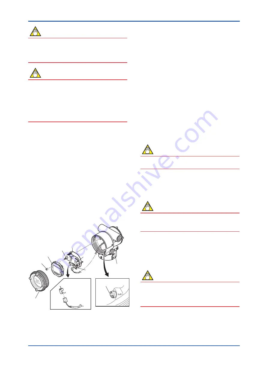
Removing the Display assembly
1) Remove the Display cover.
2) While supporting the Display assembly with one
hand, loosen its two Mounting screws.
3) Dismount the Display assembly from the CPU
assembly.
When doing this, carefully pull the Display
assembly straight forward so as not to damage
the connector pins between it and the CPU
assembly.
■
Attaching the Display assembly
1) Align both the Display assembly and CPU
assembly connectors and engage them.
2) Insert and tighten the two Mounting screws.
3) Replace the Display cover.
F1002.ai
Boss
Display
assembly
Mounting
screw
CPU
assembly
Bracket
(for
scroll
knob
screw
pin)
Slide
switch
Display
Cover
Output terminal
cable
scroll knob
screw pin
scroll knob
Figure 10.2 Removing and Display Assembly and
CPU Assembly
10.2.2 Replacing the CPU Board
Assembly
This subsection describes the procedure for
replacing the CPU assembly. (See figure 10.2)
■
Removing the CPU Assembly
1) Remove the Display cover.
2) Turn the Scroll knob screw to the position
(where the screw head slot is horizontal) as
shown in figure 10.2.
3) Disconnect the Output terminal cable (cable
with brown connector at the end). When doing
this, lightly press the side of the CPU assembly
connector and pull the cable connector to
disengage.
4) Use a socket driver (width across flats, 5.5mm)
to loosen the two bosses.
5) Carefully pull the CPU assembly straight
forward to remove it.
NOTE
Be careful not to apply excessive force to the
CPU assembly when removing it.
■
Mounting the CPU Assembly
1) Connect the output terminal cable (with brown
connector).
NOTE
Make certain that the cables do not get pinched
between the case and the edge of the CPU
assembly.
2) Align and engage the scroll knob screw pin
with the groove on the bracket on the CPU
assembly. Then insert the CPU board assembly
straight onto the post in the case.
3) Tighten the two bosses.
NOTE
Confirm that the scroll knob screw pin is placed
properly in the groove on the bracket prior to
tightening the two bosses. If it is not, the display
scroll mechanism will be damaged.
4) Replace the Display cover.
Summary of Contents for FVX110
Page 1: ...User s Manual FVX110 Fieldbus Segment Indicator IM 01S01C01 01EN IM 01S01C01 01EN 4th Edition ...
Page 15: ... 2 Handling Cautions 2 4 IM 01S01C01 01EN ...
Page 16: ... 2 Handling Cautions 2 5 IM 01S01C01 01EN ...
Page 17: ... 2 Handling Cautions 2 6 IM 01S01C01 01EN ...
Page 18: ... 2 Handling Cautions 2 7 IM 01S01C01 01EN ...
Page 19: ... 2 Handling Cautions 2 8 IM 01S01C01 01EN ...