


IM 01C25R01-01E
2-3
2. About Multivariable Transmitter
2.3 Flow Calculation
There are two flow calculation modes: auto compensa-
tion mode and basic mode.
The EJXMVTool mass flow configuration software is
required to configure auto compensation mode.
(Please refer to IM 01C25R50-01E for FSA210.)
Sections 2.4 and 2.5 give an overview of the two
calculation functions and explain how to configure
them.
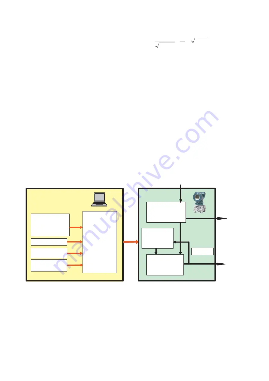
2.4 Auto Compensation Mode
Configuration of the fluid physical properties and the
EJX910A primary device can be performed from an
EJXMVTool dialog window. In auto compensation
mode, all flow factors for flow calculation are dynami-
cally compensated to an optimum value with a high
level of accuracy. The flow factors that are automati-
cally compensated are discharge coefficient, diameter
of primary device, upstream internal pipe diameter, gas
expansion factor, density, and viscosity.
Based Mass Flow Equation
Qm =
ε
d
2
2
∆
P
C
(1–
4
)
π
4
C,
,
ε
, d and
are dynamically compensated flow
factor.
Qm: Mass Flow
C: Discharge coefficient
: Diameter ratio
ε
: Expansion factor
d: Diameter of orifice
∆
P: Differential Pressure
: Density of fluid
Volume Flow Equation
Qv = Qm /
EJXMVTool
Physical propertyDB
Diff pressure (DP)
Static pressure (SP)
Temperature (T)
Fluid condition
Flow calculation
standard
Primary element
information
Transmitter
coefficient
Flow
calculation
EJX910A
Transmitter
coefficient
Sensor input (DP, SP, Temp )
Output for
selected PV.
DP, SP, ET
Mass flow
Dippr
Steam Table
Natural Gas
Optimization
F0203E.EPS
Figure 2.3 Auto Compensation Mode Block Diagram


