


2-5
DIGITAL OPERATOR
DESCRIPTION
KEY SEQUENCE
DISPLAY
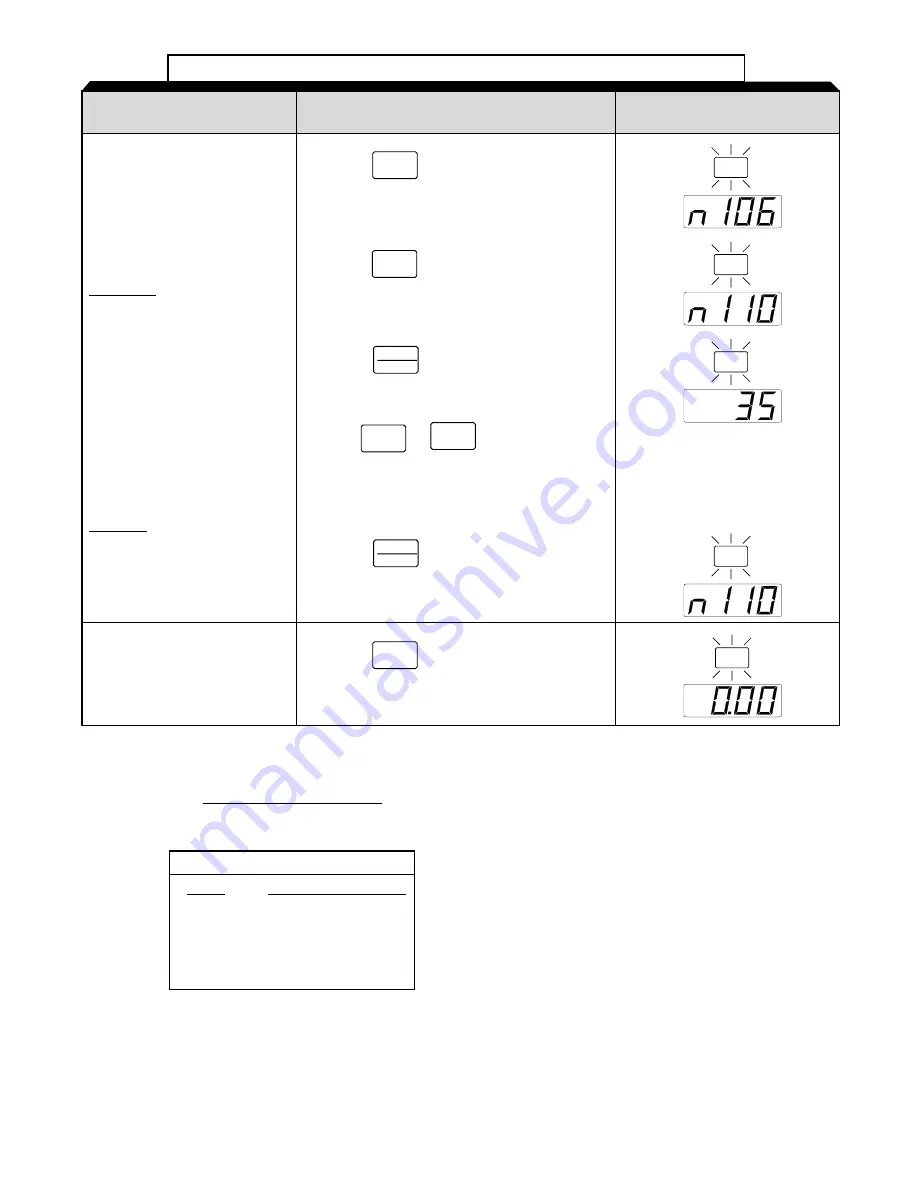
Table 2-1. Open Loop Vector Startup Procedure - Continued
Set the motor “no load cur-
rent” in the drive.
Motor no load current is set
as a percentage of motor
rated current. It is calculated
using the formula:
I
noload
*100 = n110
I
rated
Where:
I
noload
= Motor no load current
(measured in the
previous step)
I
rated
= Motor rated current
(from motor
nameplate)
Example:
2.5 * 100 = 60
4.2
Press the
key four times.
DSPL
This completes the startup.
Make further programming
changes as required.
Press the
key to get out of the pro-
gramming mode.
DSPL
(1)
The number in the display may be different than shown.
(2)
Motor synchronous speed can be calculated using the following formula:
120 x motor rated frequency
synch. speed =
number of motor poles
For 60 Hz Rated Motors
Poles
Synchronous Speed
2
3600 RPM
4
1800 RPM
6
1200 RPM
8
900 RPM
PRGM
PRGM
PRGM
PRGM
FREF
Press the
key.
DATA
ENTER
Press the
key.
Use the
&
keys until the
number in the display matches calculated no-
load current.
V
V
DATA
ENTER
Press the
key four times.
V
(1)
(1)
Summary of Contents for SI-T/ V7
Page 1: ...V7 and V74X Drives Technical Manual Models MV and CIMR V7 Document Number TM V7 01...
Page 16: ...xiv Intentionally Left Blank...
Page 18: ...xvi...
Page 22: ...1 4 Continued 1 3 PHYSICAL INSTALLATION Figure 1 1b Component Identification...
Page 31: ...1 13 Continued 1 4 ELECTRICAL INSTALLATION Figure 1 4 Installation of Line Filter and V7 Drive...
Page 36: ...1 18...
Page 48: ...3 2...
Page 52: ...4 4...
Page 97: ...5 45 PID Block Diagram 5 28 PID CONTROL Continued...
Page 120: ...6 10...
Page 128: ...A1 8...
Page 132: ...A3 2...
Page 144: ...A6 6...
Page 148: ...A7 4...
Page 152: ...A8 4...
Page 156: ...I 4...


