


- viii -
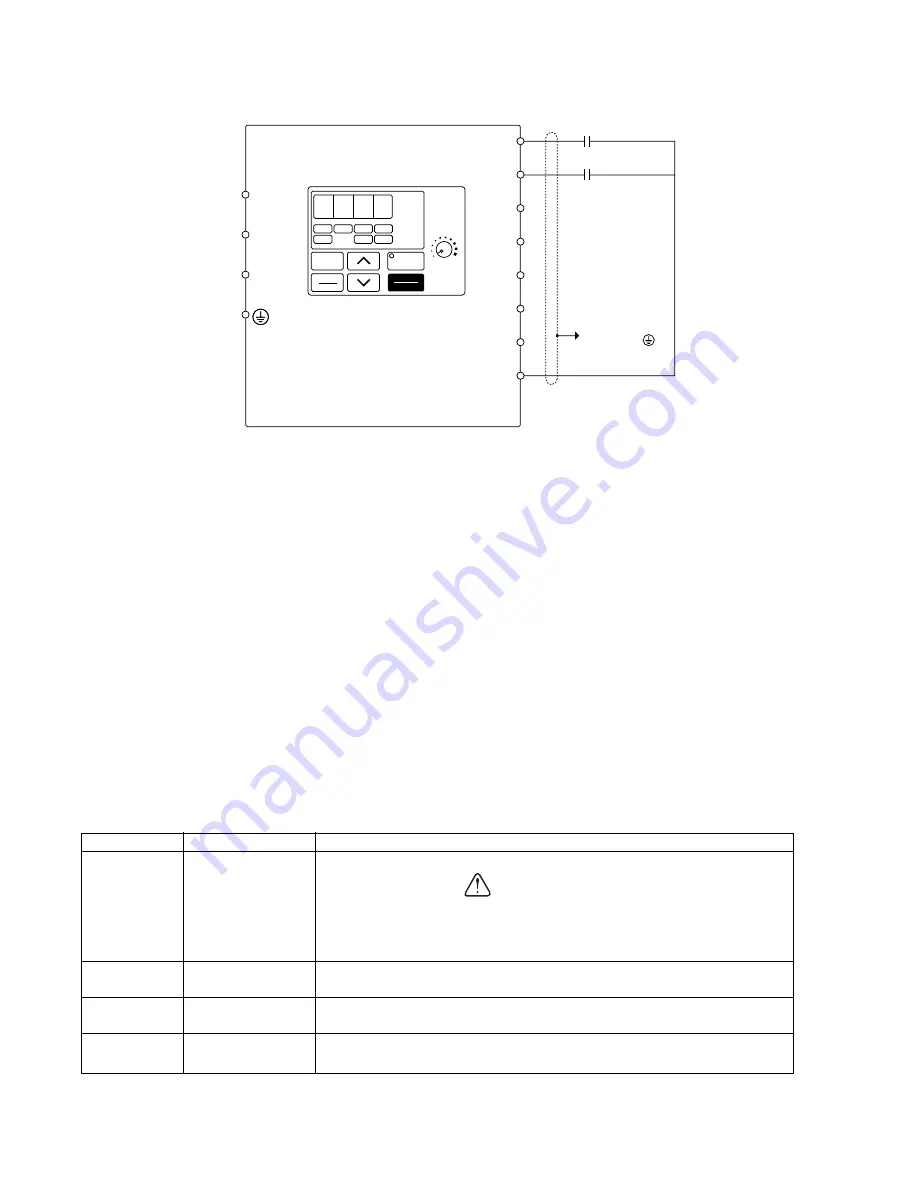
Example 2: Remote Sequence (2-Wire) & Local Reference (Digital
Operator)
This configuration is used when the sequence comes from a remote source, such as a relay or a PLC. It can
also be used with a maintained switch when it is desirable to have the drive restart on restoration of power. It
should not be used where safety of attending personnel might be threatened by a restart.
OPERATION:
• The frequency reference comes from the digital operator pot.
• Close (K1) to Run Forward at frequency set by the digital operator pot.
• Close (K2) to Run Reverse at frequency set by the digital operator pot.
• If both (K1) & (K2) are closed, the drive stops and displays the error message: “EF”
• If the drive is put in the “Local” mode using the LO/RE quick start LED, the drive will behave the same as
illustrated in Example 1.
Table 3: Programming Required For Remote 2-wire Sequence & Local Reference
FS
FR
FC
DATA
ENTER
DSPL
RUN
MIN
MAX
REV
FWD
Forward Run
Reverse Run
(K1)
S1
S2
S3
S4
S5
S6
S7
SC
STOP
RESET
FREF
FOUT
IOUT
MNTR
PRGM
LO/RE
F/R
Shield (Drain Wire)
To Terminal
Control Wiring Schematic
0. 0 0
(K2)
Parameter
Display
Description
n001
10
n001
4
n004
0
n036
Set Motor FLA
The drive will perform a 2-wire reset.
Setting this value will reset all parameters to their original factory
settings (all previous adjustments will be lost) When the drive
completes the reset, this parameter returns to a value of 1.
CAUTION
After doing the reset above, the password parameter returned to a
1. Change it to a 4 to get access to all parameters in the drive.
This parameter sets the reference (motor speed) to come from the
digital operator potentiometer (local).
Enter the motor’s full load amps (as shown on the motor
nameplate).
Summary of Contents for SI-T/ V7
Page 1: ...V7 and V74X Drives Technical Manual Models MV and CIMR V7 Document Number TM V7 01...
Page 16: ...xiv Intentionally Left Blank...
Page 18: ...xvi...
Page 22: ...1 4 Continued 1 3 PHYSICAL INSTALLATION Figure 1 1b Component Identification...
Page 31: ...1 13 Continued 1 4 ELECTRICAL INSTALLATION Figure 1 4 Installation of Line Filter and V7 Drive...
Page 36: ...1 18...
Page 48: ...3 2...
Page 52: ...4 4...
Page 97: ...5 45 PID Block Diagram 5 28 PID CONTROL Continued...
Page 120: ...6 10...
Page 128: ...A1 8...
Page 132: ...A3 2...
Page 144: ...A6 6...
Page 148: ...A7 4...
Page 152: ...A8 4...
Page 156: ...I 4...


