


5-10
The Drive allows selection of up to twenty-three frequency references. Three are analog inputs,
sixteen are digital presets (selected with multi-function inputs), one is a jog input, one is a pulse
train input, one is via serial communications (MODBUS), and one is from an option cable (see
paragraph 5.32).
A.
Frequency Reference via Analog Input
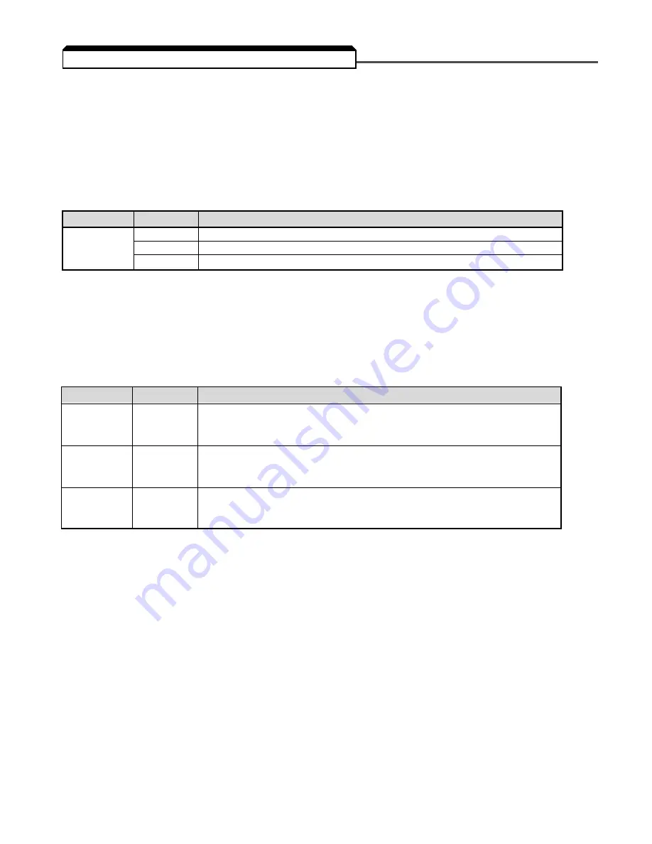
In order to set the Drive so the frequency reference comes from the analog input, set parameter
n004 as shown in the table below:
(1)
SW2 consists of two separate slide switches and can be found just above the upper row of control circuit terminals.
The switch towards the bottom (labeled “2”) connects a 250
Ω
resistor from terminal FR to FC when set to the “on”
position (to the right). NOTE: All power must be removed from the Drive before SW2 can be set.
B.
Frequency Reference via Digital Presets
In order to set the Drive so the frequency reference comes from the digital presets, the following
parameters need to be set:
Depending upon how many preset references are required determines the actual settings of n050
thru n056. Several examples are listed below.
PARAMETER
SETTING
DESCRIPTION
n024
User
thru
Set
Eight Frequency References
n031
n050
6, 7, 8,
Sets the multi-function inputs so selection of the various references is
thru
and/or
possible with contact closures.
n056
9
n120
User
thru
Set
Eight More Frequency References
n127
PARAMETER
SETTING
DESCRIPTION
2
Sets terminal FR for a voltage input (0 to 10V) Set SW2 switch 2 to Off
(1)
n004
3
Sets terminal FR for a current input (4 to 20mA) Set SW2 switch 2 to On
(1)
4
Sets terminal FR for a current input (0 to 20mA) Set SW2 switch 2 to On
(1)
5.11 FREQUENCY REFERENCE SELECTION
Summary of Contents for SI-T/ V7
Page 1: ...V7 and V74X Drives Technical Manual Models MV and CIMR V7 Document Number TM V7 01...
Page 16: ...xiv Intentionally Left Blank...
Page 18: ...xvi...
Page 22: ...1 4 Continued 1 3 PHYSICAL INSTALLATION Figure 1 1b Component Identification...
Page 31: ...1 13 Continued 1 4 ELECTRICAL INSTALLATION Figure 1 4 Installation of Line Filter and V7 Drive...
Page 36: ...1 18...
Page 48: ...3 2...
Page 52: ...4 4...
Page 97: ...5 45 PID Block Diagram 5 28 PID CONTROL Continued...
Page 120: ...6 10...
Page 128: ...A1 8...
Page 132: ...A3 2...
Page 144: ...A6 6...
Page 148: ...A7 4...
Page 152: ...A8 4...
Page 156: ...I 4...


