background image

3-1

165553-1CD

HW1482183

3

Teaching

3.1 Registering Instructions

Conveyor Synchronized 
Funciton with Shift 
Functions

3

Teaching

3.1

Registering Instructions

The instructions can be registered when the cursor is in the address area 
on the job content display in teach mode.

3.1.1 SYSTART Instruction

Function

The SYSTART instruction starts the conveyor synchronized control.  The 
manipulator starts follow-up motion by a move instruction after the 
SYSTART instruction, or TIMER or WAIT instruction.

When this instruction is executed, the manipulator stops and waits until 
the conveyor current position value exceeds the synchronization start 
position value.  When the conveyor current position value exceeds the 
synchronization start position value, the manipulator starts the follow-up 
motion.

When the conveyor current position value exceeds the synchronization 
start position value within the tolerance (OL) at the moment the SYSTART 
instruction is executed, the manipulator starts the follow-up motion from 
the point the SYSTART instruction is executed.

When the conveyor current position value exceeds the synchronization 
start position value beyond the tolerance (OL) at the moment the 
SYSTART instruction is executed, the system variable $B008 is reset to 
“0,” and the manipulator executes the proceeding instruction without the 
synchronized motion.  At the normal completion, “1” is set to the system 
variable $B008.

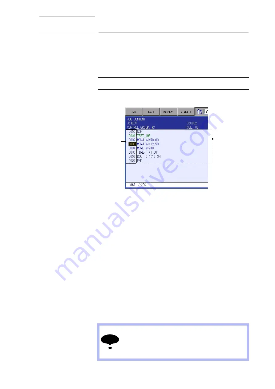
Select {JOB} under the main menu


Select {JOB CONTENT}


Move 

the cursor to the address area

Address area

Instruction area

NOTE

The system variable $B008 cannot be read directly. Copy 
the system variable to Bxxx by using a GETS instruction 
and read the value.

<Example> GETS B000 $B008
                    JUMP *NG IF B000<1

43 of 98

Summary of Contents for Motoman DX200

Page 1: ...t of the product and prior to initial operation read these instructions thoroughly and retain for future reference MOTOMAN INSTRUCTIONS MOTOMAN INSTRUCTIONS DX200 INSTRUCTIONS DX200 OPERATOR S MANUAL for each purpose DX200 MAINTENANCE MANUAL The DX200 operator s manual above corresponds to specific usage Be sure to use the appropriate manual 1 of 98 ...

Page 2: ...ware This manual is copyrighted property of YASKAWA and may not be sold or redistributed in any way You are welcome to copy this document to your computer or mobile device for easy access but you may not copy the PDF files to another website blog cloud storage site or any other means of storing or distributing online content Printed in the United States of America First Printing 2016 YASKAWA Ameri...

Page 3: ...r shields removed for clarity Be sure all covers and shields are replaced before operating this product The drawings and photos in this manual are representative examples and differences may exist between them and the delivered product YASKAWA may modify this model without notice when necessary due to product improvements modifications or changes in specifications If such modification is made the ...

Page 4: ...The customer is responsible for providing adequately trained personnel to operate program and maintain the equipment NEVER ALLOW UNTRAINED PERSONNEL TO OPERATE PROGRAM OR REPAIR THE EQUIPMENT We recommend approved YASKAWA training courses for all personnel involved with the operation programming or repair of the equipment This equipment has been tested and found to comply with the limits for a Cla...

Page 5: ... hazardous situation which if not avoided could result in death or serious injury to personnel WARNING Indicates a potentially hazardous situation which if not avoided could result in death or serious injury to personnel CAUTION Indicates a potentially hazardous situation which if not avoided could result in minor or moderate injury to personnel and damage to equipment It may also be used to alert...

Page 6: ...nt maximum envelope of the manipulator Be sure to use a lockout device to the safeguarding when going inside Also display the sign that the operation is being performed inside the safeguarding and make sure no one closes the safeguarding View the manipulator from the front whenever possible Always follow the predetermined operating procedure Keep in mind the emergency response measures against the...

Page 7: ...found repair them immediately and be sure that all other necessary processing has been performed Check for problems in manipulator movement Check for damage to insulation and sheathing of external wires Always return the programming pendant to the hook on the cabinet of the DX200 after use The programming pendant can be damaged if it is left in the manipulator s work area on the floor or near fixt...

Page 8: ... manual names of companies corporations or products are trademarks registered trademarks or brand names for each company or corporation The indications of R and TM are omitted Equipment Manual Designation Programming Pendant Character Keys Symbol Keys The keys which have characters or its symbol printed on them are denoted with ex ENTER Axis Keys Numeric Keys Axis Key and Numeric Key are generic n...

Page 9: ... E Stop mode whenever it is not in use In accordance with ANSI RIA R15 06 2012 section 4 2 5 Sources of Energy use lockout tagout procedures during equipment maintenance Refer also to Section 1910 147 29CFR Part 1910 Occupational Safety and Health Standards for General Industry OSHA Mechanical Safety Devices The safe operation of this equipment is ultimately the users responsibility The conditions...

Page 10: ...on programs or jobs a backup must always be made before any service procedures are done and before any changes are made to options accessories or equipment Any modifications to the controller unit can cause severe personal injury or death as well as damage to the robot Do not make any modifications to the controller unit Making any changes without the written permission from YASKAWA will void the ...

Page 11: ...y YASKAWA trained qualified personnel Summary of Warning Information This manual is provided to help users establish safe conditions for operating the equipment Specific considerations and precautions are also described in the manual but appear in the form of Dangers Warnings Cautions and Notes It is important that users operate the equipment in accordance with this instruction manual and any addi...

Page 12: ...ease allow approximately 24 to 36 hours for a response to your inquiry Please have the following information ready before you call Customer Support techsupport motoman com NOTE Please use e mail for routine inquiries only If you have an urgent or emergency need for service replacement parts or information you must contact YASKAWA Customer Support at the telephone number shown above System Conveyor...

Page 13: ...Detection Function for BROKEN LINE DETECT Status Conveyor Pulse 2 9 2 5 Conveyor Supplemental Condition File 2 10 2 6 Start Shift Condition File 2 11 2 7 Editing the Start Shift Condition File 2 14 2 7 1 Display of the Start Shift Condition File 2 14 2 7 2 Editing the Start Shift Condition File 2 14 2 8 WORK ID SHIFT Condition File 2 15 2 9 Editing the WORK ID SHIFT Condition File 2 18 2 9 1 Displ...

Page 14: ...ft Function 3 14 3 8 3 Job Example Using the Start Shift WORK ID Shift and WORK IN NOT Shift Functions Shipment Before DN1 60 00 3 16 3 8 4 Job Example Using the Start Shift WORK ID Shift and WORK IN NOT Shift Functions New Shipment at DN1 60 00 or Later 3 19 3 9 Manual Setting Function for Conveyor Position 3 20 3 9 1 Manual Setting Procedure for the Conveyor Position 3 21 3 9 2 Precautions 3 21 ...

Page 15: ...3 CV WORK ID SHIFT STATUS Display 5 10 5 3 1 Deleting a Conveyor WORK ID Shift Data 5 11 5 3 2 Deleting the Shift Data and the Data of Conveyor Synchronized Section 5 12 5 4 CV WORK IN NOT SHIFT STATUS Display 5 13 5 4 1 Deleting a Conveyor WORK IN NOT Shift Data 5 14 5 5 CV SHIFT MONITOR display 5 15 5 5 1 Switching the Reference Workpiece for Synchronization 5 16 5 5 2 Deleting a Data of Conveyo...

Page 16: ...n with the conveyor movement When the conveyor synchronized function is used with shift functions it is useful for a situation where the conveyor home position limit switch the workpiece identification detecting limit switch WORK ID detecting limit switch and the workpiece detecting limit switch WORK IN NOT detecting limit switch cannot be installed near the manipulator Using the conveyor synchron...

Page 17: ...rmation of all the workpieces that passed the conveyor home position limit switch and starts the job programmed for each workpiece when the corresponding workpiece reaches the manipulator start position so that the manipulator executes the job in the follow up motion to the conveyor For the above control the start shift function manages up to 99 workpiece position data from the conveyor home posit...

Page 18: ...programmed for each workpiece when the corresponding workpiece reaches the manipulator start position so that the manipulator executes the job in the follow up motion to the conveyor For the above control the WORK ID shift function manages the WORK ID information up to 99 workpieces in the section from the WORK ID detecting limit switch to the reference workpiece for synchronization start Setting ...

Page 19: ...NOT detecting limit switch When the DX200 receives the information that a workpiece is in the skit the DX200 starts the job for the workpiece to move the manipulator in synchronization with the conveyor For the above control the WORK IN NOT shift function manages up to 99 skit data in the section from the WORK IN NOT detecting limit switch to the reference workpiece for synchronization start Setti...

Page 20: ...F Take this into account when activating the function after the power is ON When all the shift functions such as Start Shift function WORK ID Shift function and WORK IN NOT Shift function are disabled set to NOT USED the DX200 operates in the same way as the operation with the basic conveyor synchronized function without shift functions However the job preparing method is different from the convey...

Page 21: ...to CH1 the WORK ID detecting limit switch to CH2 and the WORK IN NOT detecting limit switch to CH3 each limit switch can be connected to any connector from CH1 to CH3 on the conveyor synchronization board JANCD YCP02 Also more than two different limit switches can be connected to one connector Which limit switch is to be connected to which connector can be specified in the conveyor supplemental co...

Page 22: ...r not 5 ENCODER INPUT ENCODER VIRTUAL ENCODER Specify whether the actual encoder input or a virtual pulse encoder is used for the conveyor synchronized control If the virtual pulse encoder is selected the manipulator can execute the synchronized motion to the conveyor even if the encoder is not connected or the conveyor is not running which can be used for confirming the manipulator motion at the ...

Page 23: ...ormed 9 USER COORD NO 1 to 63 When ROBOT AXIS is selected in 8 specify the user coordinate number in whose X axis direction the manipulator moves in synchronization with the conveyor movement 10 BASE AXIS X Y Z When BASE AXIS is selected in 8 specify X Y or Z axis to move in synchronization with the conveyor movement 11 POS RESOLUTION 0 to 999 99 μm pulse This data convert one pulse from the encod...

Page 24: ...limit for encoder reset signal monitoring 15 CV SPEED DOWN MODE EXECUTE ALARM PAUSE JOB JOB INTERRUPTION AFTER OPERATION Specify the action of the manipulator when the conveyor speed is lowered below the conveyor speed lower limit set in 16 EXECUTE Regardless of the conveyor speed the manipulator executes the job When the conveyor stops the manipulator continues the synchronized motion with the co...

Page 25: ...ual encoder not used 001 to 4096 The general purpose input signal of the set number activates the virtual encoder mode 18 VIRTUAL ENCODER OUT 0 to 4096 When VIRTUAL ENCODER is selected in 5 set the general purpose output signal number to be set for the virtual encoder output 000 Virtual encoder not used 001 to 4096 The general purpose output signal of the set number is output from the virtual enco...

Page 26: ...V CONDITION Display a desired conveyor condition file1 1 Press the PAGE to display the next file number Press SHIFT the PAGE to display the previous file number Select USED STATUS USED or NOT USED is selected alternately Select PORT NO The selection dialog appears Select a desired port number Select BROKEN LINE DETECT OFF or ON is selected alternately Select ENCODER INPUT ENCODER or VIRTUAL ENCDR ...

Page 27: ...essing Numeric keys Select VIRTUAL CONVEYOR SPEED Enter a value by pressing Numeric keys Select AVERAGED TRAVEL TIME Enter a value by pressing Numeric keys Select RESET SIGNAL MONITORING TIME Enter a value by pressing Numeric keys Select CONVEYOR SPEED DOWN MODE Selection dialog box appears Select a desired mode Select CONVEYOR LOWER LIMIT SPD Enter a value by pressing Numeric keys Select VIRTUAL ...

Page 28: ...00 internally quadruples every encoder pulse number the conveyor s maximum positional resolution is 3999 96 μm pulse As the resolution error is stored as much as the conveyor travel pulse amount the setting must be correct For example when the resolution is set 0 01 μm pulse bigger the follow up error of 0 1 mm at the point that the conveyor moves for 1000 pulses The conveyor resolution is mention...

Page 29: ...nt I O ladder program or by the setting on the host controller referring to the information of these outputs The time to output the broken line detection status signal can be set Set the time to output the signal sent from the board for synchronization to the main CPU in the sensor parameter SE017 setting for output time of broken line detection signal This prevents the main CPU from failing to ge...

Page 30: ...ctions the conveyor supplemental condition file CV TRACKING COND SUPP must be set in addition to the conveyor condition file The CV TRACKING COND SUPP file consists of three files START SHIFT SET WORK ID SHIFT SET and WORK IN NOT SHIFT SET Set the files of the functions required for your system configuration START SHIFT condition file WORK ID SHIFT condition file WORK IN NOT SHIFT condition file C...

Page 31: ...HATTERING PRVNT DIS 0 to 9999 9 mm While the conveyor moves for the chattering prevention distance from the moment that the conveyor home position signal is input the next conveyor home position signal input is ignored Set 0 to disable monitoring for the chattering prevention distance and to count the number of workpieces with every input 1 2 3 4 5 6 7 Conveyor moving direction Conveyor home posit...

Page 32: ...ery input If both the distance and the time for the chattering prevention are set the larger one is applied 6 MAX WORK CNT 0 to 99 workpieces Set the maximum number of workpieces that move between the conveyor home position limit switch to the reference workpiece for synchronization start Conveyor moving direction Conveyor home position limit switch Manipulator Until this time pass from the moment...

Page 33: ...ope the home position limit switch ON signal is shifted in synchronization with the conveyor movement to the manipulator working envelope Set the distance from the conveyor home position limit switch to the shift end position When 0 is set the SYSTART instruction is executed when the conveyor home position limit switch ON signal is input Manipulator start position Conveyor moving direction START S...

Page 34: ...t CONVEYOR COND SUPP Select DISPLAY Select START SHIFT 1 1 Press the PAGE to display the next file number Press SHIFT PAGE to display the previous file number Select USED STATUS USED or NOT USED is selected alternately Select CHATTERING PREVENTION DISTANCE Enter a value by pressing Numeric keys Select CHATTERING PREVENTION TIME Enter a value by pressing Numeric keys Select MAX WORK FIND COUNT Ente...

Page 35: ...set distance from the moment the WORK ID detecting limit switch signal is input another WORK ID detecting limit switch signal is ignored Set 0 to disable monitoring for the chattering prevention distance and to count the number of workpieces with every input 5 CHATTERING PRVNT TIME 0 to 999 9 sec Set a time to prevent the repeated inputs of the WORK ID detecting limit switch signal due to the limi...

Page 36: ...ID detecting limit switch to the manipulator start position subtracted by 1 2 of the minimum workpiece pitch For the new shipment at DN1 60 00 or later set the value of the distance from the WORK ID detecting limit switch to the manipulator start position Manipulator start position Conveyor moving direction WORK SHIFT POSITION WORK ID detecting limit switch Manipulator 1 2 of the minimum workpiece...

Page 37: ...ecting limit switch to the reference workpiece for synchronization start 8 WORK ID SIG 0 to 4096 Set the head general purpose input number that specifies the WORK ID number 9 WORK ID STATUS BIT 1 to 10 Set the number of valid bits of the WORK ID number Maximum 10 bits can be set to specify up to the WORK ID number 1024 Manipulator start position Conveyor moving direction WORK ID detecting limit sw...

Page 38: ...ess the PAGE to display the next file number Press SHIFT PAGE to display the previous file number Select USED STATUS USED or NOT USED is selected alternately Select PORT NO The selection dialog appears Select a desired port number Select CHATTERING PREVENTION DISTANCE Enter a value by pressing Numeric keys Select CHATTERING PREVENTION TIME Enter a value by pressing Numeric keys Select WORK SHIFT P...

Page 39: ...or the set distance from the moment the WORK IN NOT detecting limit switch signal is input another WORK IN NOT detecting limit switch signal is ignored Set 0 to disable monitoring for the chattering prevention distance and to count the number of workpieces with every input 5 CHATTERING PRVNT TIME 0 to 999 9 seconds Set a time to prevent the repeated inputs of the WORK IN NOT detecting limit switch...

Page 40: ...tecting limit switch to the manipulator start position subtracted by 1 2 of the minimum workpiece pitch For the new shipment at DN1 60 00 or later set the value of the distance from the WORK IN NOT detecting limit switch to the manipulator start position Manipulator start position Conveyor moving direction WORK IN NOT SHIFT POSITION WORK IN NOT detecting limit switch Manipulator 1 2 of the minimum...

Page 41: ...umber of workpieces that are set between the WORK IN NOT detecting limit switch to the reference workpiece for synchronization start 8 WORK IN NOT SIG 0 to 4096 Set the general purpose output signal number that specifies the presence absence of workpiece Manipulator start position Conveyor moving direction WORK IN NOT detecting limit switch Manipulator MAX WORK FIND COUNT 41 of 98 ...

Page 42: ...WORK IN NOT SHIFT 1 1 Press the PAGE to display the next file number Press SHIFT PAGE to display the previous file number Select USED STATUS USED or NOT USED is selected alternately Select PORT NO The selection dialog appears Select a desired port number Select CHATTERING PREVENTION DISTANCE Enter a value by pressing Numeric keys Select CHATTERING PREVENTION TIME Enter a value by pressing Numeric ...

Page 43: ...ipulator starts the follow up motion When the conveyor current position value exceeds the synchronization start position value within the tolerance OL at the moment the SYSTART instruction is executed the manipulator starts the follow up motion from the point the SYSTART instruction is executed When the conveyor current position value exceeds the synchronization start position value beyond the tol...

Page 44: ...l the conveyor reaches the synchronization start position for the next SYSTART instruction When the conveyor reaches the synchronization start position the manipulator starts the follow up motion to the conveyor Format Conveyor condition file No CONVEYOR FILE Set the conveyor condition data file No to be used Synchronization start position SYNC START POS Set the conveyor position where the synchro...

Page 45: ...T POS and press SELECT Enter a desired number or value by using Numeric keys then press ENTER To add change or delete an additional item Move the cursor to the instruction in the input buffer line and press SELECT The detail edit display appears To add a tolerance select UNUSED in OVER LIMIT And then the selection dialog appears Select OL After having added or changed the additional items press EN...

Page 46: ...laces End step of the synchronization Head of the synchronizing operation line After the CVQUE instruction For the details refer to section 3 8 Job Examples on page 3 13 Format Conveyor condition file No CONVEYOR FILE Set the conveyor condition file number to be used Continuity attribute Without ON signal from the conveyor home position limit switch the DX200 executes the SYSTART instruction and t...

Page 47: ...he manipulator motion speed in playback mode Conveyor condition file number Set the conveyor condition file number to be used Conveyor position at teaching Set the conveyor position at teaching NOTE The conveyor synchronized motion can be suspended in the middle of a job To suspend the conveyor synchronized motion insert the SYEND instruction added with a tag CONT continuity attribute The manipula...

Page 48: ... may not be able to move depending on the conveyor speed or the manipulator s wrist posture In such a case reset the play speed lower 3 1 4 CVQUE Instruction Function The CVQUE instruction switches the conveyor position data which is used for the conveyor synchronized motion to the position data of the next workpiece If the next workpiece information is not set in the shift table the CVQUE instruc...

Page 49: ...IFT MOTION TYPE The interpolation mode displayed in the input buffer line switches between the standard interpolation and the interpolation for synchronized motion Then each time MOTION TYPE is pressed the interpolation mode changes as SYMOVJ SYMOVL SYMOVC NOTE For the shipment before DN1 60 00 when the CVQUE instruction is executed the first information of the WORK ID shift data and WORK IN NOT s...

Page 50: ...the manipulator motion speed and the conveyor moving direction 3 3 Wrist Posture in Conveyor Synchronized Section In the conveyor synchronized section the manipulator wrist maintains its taught posture while the manipulator moves in synchronization with the conveyor movement Teach a posture so that the wrist can be moved in the conveyor moving direction For further information on the wrist posture...

Page 51: ...e to a teaching position The position where the conveyor home position limit switch is turned ON is automatically registered as the conveyor home position Conveyor home position limit switch Conveyor moves Start shift distance Manipulator start position Conveyor synchronized section Conveyor synchronized section Conveyor synchronized section Conveyor home position limit switch The conveyor home po...

Page 52: ...rom the manipulator start position is displayed in the column No 1 2 Move the conveyor Then stop the workpiece at the teaching position after the conveyor home position limit switch is turned ON At the moment the conveyor home position limit switch is turned ON make sure that 0 is displayed in CURR POS PULSE on the conveyor position display and the counter is reset When using the start shift funct...

Page 53: ...interruption of synchronized motion 2 Perform another teaching for other workpiece For the details of the above operations refer to section 5 6 Teaching After Interruption of Playback in Synchronized Operation of DX200 OPTIONS INSTRUCTION FOR CONVEYOR SYNCHRONIZED FUNCTION SYMOVL V 100 0 CV 1 CTP 1000 000 0005 NOTE When the start shift function is not used as long as the conveyor synchronized oper...

Page 54: ...ted However this condition cannot be satisfied with conveyor synchronized motion move instructions This is because a taught position for a conveyor synchronized motion move instruction is interpreted to different step positions on the conveyor position as explained before Therefore ordinary deleting operation is not possible To delete a conveyor synchronized move instruction press MODIFY to change...

Page 55: ...0 1 and an error occurred if B000 0 0005 JUMP END IF B000 0 If B000 0 the synchronization did not start normally jumps to the label END 0006 SYMOVL CV 1 CTP 50 000 Move instruction for the conveyor synchronized motion 0007 The manipulator moves in synchronization with the conveyor 0008 SYMOVL CV 1 CTP 50 000 0009 END Jumps here if the conveyor synchronization did not start normally 0010 SYEND CV 1...

Page 56: ...dicate whether the synchronization has started normally or not The contents of B008 is copied to B000 Synchronization started normally if B000 1 and an error occurred if B000 0 0006 JUMP END IF B000 0 If B000 0 the synchronization did not start normally jumps to the label END 0007 CALL JET 1 ENTRY 18 Starts the work job registered in the job registration table 1 0008 END Jumps here if the conveyor...

Page 57: ...r the conveyor synchronized motion 0008 SYSTART CV 1 STP 2000 00 Waits for the synchronization start of module 2 The manipulator stops and waits until the conveyor reaches the specified position 0009 SYMOVL CV 1 CTP 2000 00 Move instruction for the conveyor synchronized motion 0010 SYMOVL CV 1 CTP 2000 00 Move instruction for the conveyor synchronized motion 0011 END NOTE Do not insert the instruc...

Page 58: ...s not completed jumps to TOP 0008 CVQUE CV 1 Switches the reference workpiece for synchronization 0009 SYEND CV 1 The position table of the workpiece becomes invalid in case there is no following position data of the workpiece 0010 GETS I012 I012 Gets the WORK IN NOT information and stores to I012 0011 GETS I018 I018 Gets the WORK ID information and stores to I018 0012 JUMP TOP IF I012 0 If no wor...

Page 59: ...aracteristic file 1 to to I023 Corresponds to the conveyor WORK ID characteristic file 6 Manipulator start position Conveyor moving direction 3 Manipulator Conveyor synchronized section 4 Reference Workpiece for current synchronization 2 1 WORK ID shift section WORK IN NOT shift section I006 I000 After executing CVQUE when the next reference workpiece for synchronization start passes the WORK ID s...

Page 60: ...pletes the respective shift sections Executing the CVQUE instruction sets the head information of WORK IN NOT shift data and WORK ID shift data to the system variables I012 and I018 respectively and switches the reference workpiece for synchronization start to the next reference workpiece NOTE When the conveyor synchronized function with shift function is valid insert the CVQUE instruction and the...

Page 61: ...ned with GETCVSFT jumps to TOP 0006 JUMP END IF I001 0 If the WORK IN NOT information is NOT jumps to END 0007 SYSTART CV 1 STP 100 00 OL 100 0 Start instruction for the conveyor synchronization Starts the conveyor synchronized control when the conveyor reaches the specified position 0008 GETS B000 B008 The system variable to indicate whether the synchronization has started normally or not The con...

Page 62: ...modify the taught job When the taught job is modified by using the manual setting function for conveyor position the newly set value of the conveyor position is registered to the value of CTP when the registration of the move instruction for the synchronized motion SYMOV is modified CV Displays the conveyor characteristic file number CV 1 to 3 CURRENT mm Displays the conveyor s current position in...

Page 63: ...in the figure below When the shift functions are not used it is defined as the distance from the conveyor home position limit switch When the conveyor moves in the manual setting mode for conveyor position the pulse value of the actual conveyor is read out and the actual conveyor status on the conveyor shift table and the synchronization table are updated Move the cursor to the desired value in th...

Page 64: ...yor condition file to VIRTUAL ENCODER Or specify the virtual encoder by the general purpose input signal Refer to section 2 2 Editing Conveyor Condition File for the setting method 2 Turn ON the conveyor home position limit switch of the actual conveyor 3 Select a job for which the test run is to be carried out and open its JOB CONTENT display Press INTERLOCK and TEST START at the same time The vi...

Page 65: ...e distance can be temporally changed to 0 In this way only the manipulator s motion can be confirmed by the test run without waiting the manipulator to move for the start shift distance Set 1 for the sensor parameter SE016 Ignorance of shift distance in virtual conveyor mode so that the start shift distance is changed to 0 in the virtual encoder mode 2 3 1 0 0 Start shift distance Actual conveyor ...

Page 66: ...ndicates the conveyor home position input signal number STATUS Displays the conveyor home position input signal status or inputs the conveyor home position input signal 2 Move the cursor to the limit switch number connected to the conveyor home position input signal that is set in PORT NO in the conveyor condition file 3 By pressing INTERLOCK and SELECT at the same time select ON status to pseudon...

Page 67: ... remains below the set value in CONVEYOR LOWER LIMIT SPD for 0 1 second the job execution is interrupted only the execution of move instructions in the job are suppressed and the manipulator continues only follow up motion in the conveyor moving direction When the conveyor speed recovers to the set value in CONVEYOR LOWER LIMIT SPD or higher the job execution restarts PAUSE JOB AFTER APRAY OFF Whe...

Page 68: ...the manipulator actual dimensions and the dimensions registered in the DX200 Conversion resolution error that occurs when converting the pulse data from the conveyor encoder to the conveyor travel amount in mm Manipulator mechanical accuracy such as arm bending Follow up delay due to the conveyor speed fluctuation Manipulator system lag time Difference between the conveyor moving direction and the...

Page 69: ...the control power supply is turned OFF Even if a manipulator stops in the cases explained in the previous section the conveyor synchronized status remains Note that a manipulator performs the synchronized motion by SYMOV instruction even if the cursor is moved in teach mode the master job is called or a job selection is made 4 6 Continuance of Parallel Shift Status The parallel shift status in the...

Page 70: ...of workpieces the position information WORK ID information and WORK IN NOT information of the workpiece are automatically deleted from the job queue data Set the maximum workpiece position in the sensor parameter SxE13 3 4 n 1 2 1 n Max workpiece position Max workpiece position Workpiece shift distance WORK ID WORK ID detecting limit switch Shift completion position STP 0 Conveyor moving direction...

Page 71: ...Open the CV SHIFT MONITOR Display Open the CV SHIFT MONITOR Display in the following manner Displayed in new units shipped with version DN1 60 000 and later Select ROBOT under the main menu Select CV SYNCHRONIZATION The conveyor synchronization section monitor display appears Open the desired display1 1 Pressing the PAGE switches the display Pressing SHIFT PAGE returns to the previous display Not ...

Page 72: ...in synchronization and the manipulator start position in mm When the painting operation for the first workpiece in synchronization is completed and the CVQUE instruction is executed the workpiece for synchronization is switched to the next workpiece WORK ID INFORMATION Displays the WORK ID information of the detected workpiece in synchronization When the CVQUE instruction is executed after the job...

Page 73: ... operation procedure below The synchronization before switching the reference workpiece for synchronization is shown in the figure below The workpiece for the current synchronization is the first workpiece on the conveyor synchronized section display Press the area key Select DATA Select SYNCHRONIZATION SWITCH 1 1 Press the area key move the cursor to DISPLAY and press SELECT to open the desired d...

Page 74: ...N SWITCH and UNDO operation is not possible Observe the above precaution when SYNCHRONIZATION SWITCH is executed SYNCHRONIZATION SWITCH is valid only when two or more workpieces are in the conveyor synchronized section Do not execute SYNCHRONIZATION SWITCH operation when only one workpiece is in the conveyor synchronized section Doing so causes an alarm because no workpiece exists to be switched M...

Page 75: ...data while the conveyor is moving does not cause a problem However it may cause a malfunction due to inconsistency between the actual conveyor status and the DX200 conveyor data in the following cases The conveyor moves while power is not supplied to the DX200 or during the DX200 start sequence A momentary power failure occurs during operation in play mode The virtual conveyor mode is set with the...

Page 76: ...llowing display appears NOTE While power is supplied to the DX200 the DX200 manages and updates automatically all the conveyor data regardless of the operation mode Accordingly deleting data while the conveyor is moving does not cause a problem However it may cause a malfunction due to inconsistency between the actual conveyor status and the DX200 conveyor data in the following cases The conveyor ...

Page 77: ...t are detected by the start shift function and in the start shift section WORKPIECE No Displays the detected start shift workpiece number WORK POS PULSE Displays the distance between the detected workpiece position and the manipulator start position in pulses WORK POS mm Displays the distance between the detected workpiece position and the manipulator start position in mm When the first workpiece ...

Page 78: ...rdingly deleting data while the conveyor is moving does not cause a problem However it may cause a malfunction due to inconsistency between the actual conveyor status and the DX200 conveyor data in the following cases The conveyor moves while power is not supplied to the DX200 or during the DX200 start sequence A momentary power failure occurs during operation in play mode The virtual conveyor mod...

Page 79: ...g display appears NOTE While power is supplied to the DX200 the DX200 manages and updates automatically all the conveyor data regardless of the operation mode Accordingly deleting data while the conveyor is moving does not cause a problem However it may cause a malfunction due to inconsistency between the actual conveyor status and the DX200 conveyor data in the following cases The conveyor moves ...

Page 80: ...the WORK ID shift section WORKPIECE No Displays the detected WORK ID shift workpiece number WORK POS PULSE Displays the distance between the detected workpiece position and the manipulator start position in pulses WORK POS mm Displays the distance between the detected workpiece position and the manipulator start position in mm When the first workpiece in the shift section reaches the manipulator s...

Page 81: ...Accordingly deleting data while the conveyor is moving does not cause a problem However it may cause a malfunction due to inconsistency between the actual conveyor status and the DX200 conveyor data in the following cases The conveyor moves while power is not supplied to the DX200 or during the DX200 start sequence A momentary power failure occurs during operation in play mode The virtual conveyor...

Page 82: ...lowing display appears NOTE While power is supplied to the DX200 the DX200 manages and updates automatically all the conveyor data regardless of the operation mode Accordingly deleting data while the conveyor is moving does not cause a problem However it may cause a malfunction due to inconsistency between the actual conveyor status and the DX200 conveyor data in the following cases The conveyor m...

Page 83: ... shift section WORKPIECE No Displays the detected WORK IN NOT shift workpiece number WORK POS PULSE Displays the distance between the detected workpiece position and the manipulator start position in pulses WORK POS mm Displays the distance between the detected workpiece position and the manipulator start position in mm When the first workpiece in the shift section reaches the manipulator start po...

Page 84: ... mode Accordingly deleting data while the conveyor is moving does not cause a problem However it may cause a malfunction due to inconsistency between the actual conveyor status and the DX200 conveyor data in the following cases The conveyor moves while power is not supplied to the DX200 or during the DX200 start sequence A momentary power failure occurs during operation in play mode The virtual co...

Page 85: ...unction and are in the shift section WORKPIECE No Displays the workpiece number that is detected WORK POS mm Displays the distance between the detected workpiece position and the manipulator start position in mm When the workpiece in the shift section has not reached the manipulator start position the negative value is displayed and when the workpiece in the shift section reaches the manipulator s...

Page 86: ...ynchronized section display Execute SYNCHRONIZATION SWITCH switches the objective workpiece to the next workpiece as shown in the figure below Press the area key Select DATA Select SYNCHRONIZATION SWITCH NOTE The information of the workpiece for current synchronization is deleted by the execution of SYNCHRONIZATION SWITCH and UNDO operation is not possible Observe the above precaution when SYNCHRO...

Page 87: ...TE While power is supplied to the DX200 the DX200 manages and updates automatically all the conveyor data regardless of the operation mode Accordingly deleting data while the conveyor is moving does not cause a problem However it may cause a malfunction due to inconsistency between the actual conveyor status and the DX200 conveyor data in the following cases The conveyor moves while power is not s...

Page 88: ...power is supplied to the DX200 the DX200 manages and updates automatically all the conveyor data regardless of the operation mode Accordingly deleting data while the conveyor is moving does not cause a problem However it may cause a malfunction due to inconsistency between the actual conveyor status and the DX200 conveyor data in the following cases The conveyor moves while power is not supplied t...

Page 89: ...ing display appears NOTE While power is supplied to the DX200 the DX200 manages and updates automatically all the conveyor data regardless of the operation mode Accordingly deleting data while the conveyor is moving does not cause a problem However it may cause a malfunction due to inconsistency between the actual conveyor status and the DX200 conveyor data in the following cases The conveyor move...

Page 90: ...in synchronization with the conveyor Additional items CV Conveyor condition file 1 to 3 CTP Conveyor position at teaching in mm V Play speed Example SYMOVC V 200 0 CV 1 CTP 100 00 SYEND Function Ends the conveyor synchronized operation Additional items CV Conveyor condition file 1 to 3 CONT CONT continuity attribute may be omitted Example SYEND CV 1 CVQUE Function Switches the workpiece for synchr...

Page 91: ...the conveyor condition file is set to other than 0 1 and 2 2 The robot axis specified for tracking does not exist 3 The base axis specified for tracking does not exist in the job The error data other than 1 2 and 3 is an internal error Turn the power OFF then back ON If the alarm occurs again contact your YASKAWA representative 4531 UNDEFINED CONVEYOR CONDITION FILE Decimal Data 0 to 255 The conve...

Page 92: ...2 CONVEYOR POSITION LIMIT OVER Alarm occurred conveyor condition file No 1 2 or 3 The corrected conveyor position value exceeds 21 m Review the synchronization section After this alarm occurs the conveyor position is not updated Therefore the synchronized operation is not performed after the alarm is reset and the manipulator continues operation at the position where the alarm occurred 5023 CONVER...

Page 93: ...SITION LIMIT The WORK ID data of the first workpiece in the synchronized section exceeds the preset value Delete the WORK ID data in the synchronized section 1402 WORK IN NOT SHIFT DATA COUNT LIMIT OVER The current position pulse operation error in the WORK IN NOT shift data Check the WORK IN NOT shift data and the actual workpiece status 1403 WORK IN NOT SHIFT DATA POSITION LIMIT OVER The current...

Page 94: ...l Synchronization Data All the synchronization data are deleted by turning ON this signal 41022 Single Work Control Tracking Area While this signal is ON the DX200 manages only the latest information of the workpiece in the conveyor synchronized section When another workpiece passes the manipulator start position the XRC overwrites the currently stored workpiece information with the newly entered ...

Page 95: ...1420 Conveyor Speed Down Indicates that the conveyor speed falls below the lower limit of the speed that is set in the Conveyor Condition File 51430 to 51432 Disconnection Detected Indicates the detected disconnection of the conveyor pulse signals Each specific output signal corresponds to the following Conveyor Condition Files Conveyor Condition File No 1 51430 Conveyor Condition File No 2 51431 ...

Page 96: ...output 51420 turns ON when the conveyor speed falls below the set speed Units μm s S2C769 Switch the conveyor speed unit of conveyor monitor This parameter switch the conveyor speed unit of the conveyor monitor 0 The conveyor speed is displayed by mm sec 1 The conveyor speed is displayed by m min S2C770 The conveyor speed update timing of conveyor monitor This parameter change the conveyor speed u...

Page 97: ...piece is carried for this distance from the manipulator start position the DX200 automatically deletes the workpiece information from the job queue or issues the alarm Whether to automatically delete the information or issue the alarm can be selected by the setting of the sensor parameter No 14 Data overflow alarm specification While the conveyor synchronization is not executed however the workpie...

Page 98: ...1 124 475 8542 Phone 91 124 475 8500 YASKAWA India Private Ltd Robotics Division YASKAWA Electric China Co Ltd 22F One Corporate Avenue No 222 Hubin Road Huangpu District Shanghai 200021 China Phone 86 21 5385 2200 Fax 㸩86 21 5385 3299 YASKAWA Electric Thailand Co Ltd 59 1st 5th Floor Flourish Building Soi Ratchadapisek 18 Ratchadapisek Road Huaykwang Bangkok 10310 THAILAND Phone 66 2 017 0099 Fax...

Reviews: