2 DISASSEMBLY OF COMPONENTS
2 DISASSEMBLY OF COMPONENTS
EF494T TM 06/2011 edition
60
2.6.4
PTO module
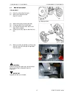
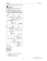
Removing PTO covers
(1)
Drain the transmission oil.
(2)
Remove the 3-point link.
(3)
Remove the draw-bar hitch and braw-bar
bracket.
(4)
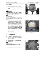
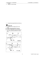
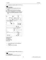
Set the PTO to first or second gear.
(5)
Remove the keeper plate and pull the shift
arm out of the PTO shift module.
NOTE:
If the PTO is left in the neutral position, the
PTO safety switch and the shift arm will hit
each other and the shift arm cannot be
pulled out.
(6)
Remove the rear cover bolts and separate
the PTO assembly.
<Reassembling>
Tightening torque: 230-300 kgf-cm
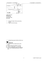
(A) Shift arm
(B) Keeper plate
(C) PTO safety switch
IMPORTANT
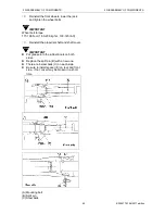
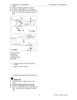
Pay attention to the clearance between the
change arm and the PTO safety switch.
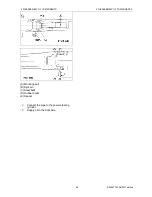
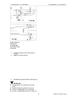
Push the change arm (C) into the PTO
module groove (A) to reassemble them. After
reassembly, move the PTO shift lever and
make sure you can change gears.
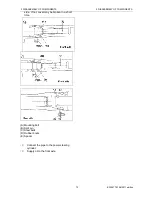
(B) PTO safety switch
(C) Change arm
Summary of Contents for EF-494T
Page 1: ...EF494T TM 06 2011 edition ...
Page 85: ...3 ENGINE 3 ENGINE EF494T TM 06 2011 edition 77 3 ENGINE ...
Page 88: ...3 ENGINE 3 ENGINE EF494T TM 06 2011 edition 80 B Return ...
Page 126: ...4 CLUTCH 4 CLUTCH EF494T TM 06 2011 edition 118 4 CLUTCH ...
Page 130: ...4 CLUTCH 4 CLUTCH EF494T TM 06 2011 edition 122 ...
Page 133: ...5 TRANSMISSION 5 TRANSMISSION EF494T TM 06 2011 edition 125 5 TRANMISSION ...
Page 167: ...7 FRONT AXLE 7 FRONT AXLE EF494T TM 06 2011 edition 159 7 FRONT AXLE ...
Page 169: ...7 FRONT AXLE 7 FRONT AXLE EF494T TM 06 2011 edition 161 7 2 CROSS SECTION VIEW ...
Page 176: ...8 POWER STEERING 8 POWER STEERING EF494T TM 06 2011 edition 168 8 POWER STEERING ...
Page 234: ...11 APPENDIXES 11 APPENDIXES EF494T TM 06 2011 edition 226 11 APPENDIXES ...
Page 235: ...11 APPENDIXES 11 APPENDIXES EF494T TM 06 2011 edition 227 11 1 HYDRAULIC CIRCUIT DIAGRAM ...
Page 236: ...228 11 2 ELECTRICAL CIRCUIT DIAGRAM 11 2 1 WIRING HARNESS ...
Page 238: ...230 11 2 3 ELECTRICAL WIRING DIAGRAM ...
Page 239: ......

