


9 HYDRAULIC LIFT UNIT
9 HYDRAULIC LIFT UNIT
EF494T TM 06/2011 edition
195
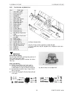
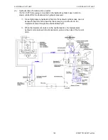
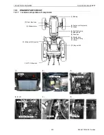
9.2.4
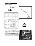
Adjusting the position feedback rod
<Adjustment>
Position control feedback
(1)
Turn hydraulic stop valve to open fully.
(2)
Start engine. Put the position control lever in
“Lowest” position and put lift arm (A) in
lowest position.
(3)
Put th
e position control lever in “Highest”
position and listen relief valve chattering
noise. If no noise, turn position feed back
rod to raise lift arm (A) until the noise
comes.
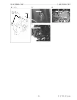
(4)
Adjust length of position feedback rod (B) so
that the free play (C) from the highest would
be 15-15mm or height of the lift arm (A) is
317 mm.
IMPORTANT
As a guide, adjust the play (C) in the lift arm (A) to
10 to 15 mm, when in the highest position.
Rod lengthened.: Lift arm lowers.
Rod shortened.: Lift arm lifts.
Note:
After each adjustment is performed, lower the lift
arm (A).
(A) Lift arm
(B) Position feed-back rod
(C) Lift arm free play
Summary of Contents for EF-494T
Page 1: ...EF494T TM 06 2011 edition ...
Page 85: ...3 ENGINE 3 ENGINE EF494T TM 06 2011 edition 77 3 ENGINE ...
Page 88: ...3 ENGINE 3 ENGINE EF494T TM 06 2011 edition 80 B Return ...
Page 126: ...4 CLUTCH 4 CLUTCH EF494T TM 06 2011 edition 118 4 CLUTCH ...
Page 130: ...4 CLUTCH 4 CLUTCH EF494T TM 06 2011 edition 122 ...
Page 133: ...5 TRANSMISSION 5 TRANSMISSION EF494T TM 06 2011 edition 125 5 TRANMISSION ...
Page 167: ...7 FRONT AXLE 7 FRONT AXLE EF494T TM 06 2011 edition 159 7 FRONT AXLE ...
Page 169: ...7 FRONT AXLE 7 FRONT AXLE EF494T TM 06 2011 edition 161 7 2 CROSS SECTION VIEW ...
Page 176: ...8 POWER STEERING 8 POWER STEERING EF494T TM 06 2011 edition 168 8 POWER STEERING ...
Page 234: ...11 APPENDIXES 11 APPENDIXES EF494T TM 06 2011 edition 226 11 APPENDIXES ...
Page 235: ...11 APPENDIXES 11 APPENDIXES EF494T TM 06 2011 edition 227 11 1 HYDRAULIC CIRCUIT DIAGRAM ...
Page 236: ...228 11 2 ELECTRICAL CIRCUIT DIAGRAM 11 2 1 WIRING HARNESS ...
Page 238: ...230 11 2 3 ELECTRICAL WIRING DIAGRAM ...
Page 239: ......


