


10 ELECTRIC EQUIPMENT
10 ELECTRIC EQUIPMENT
EF494T TM 06/2011 edition
208
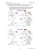
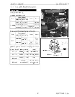
(3) 3W
(1) 3B
(2) 3R
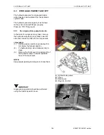
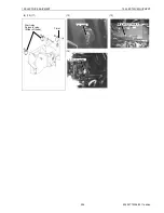
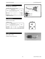
4. Fuel shut off solenoid
Stop solenoid (119653-77950)
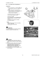
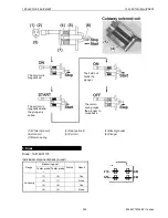
Measurements on an individual component basis (A-end coupler)
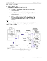
Check of the coupler on the main body side (B-end coupler)
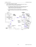
The fuel system consists of two circuits: one is the fuel
feed pump circuit that supplies the fuel to the fuel
injection pump through the filter and the other is the fuel
shut-off solenoid circuit that activates the stop lever of
the governor.
The fuel shut-off solenoid allows the operator to start or
stop the diesel engine using the starter switch only. This
is a dual-coil type solenoid having a fail-safe feature; if a
failure occurs in the electric system, the return spring in
the solenoid will cause the engine to stop.
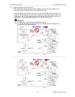
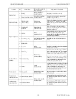
Range
Measuring point
Status
Result
Tester probe
+
Tester probe
Ω
(2)
(1)
Approx.12.4
Ω
Ω
(3)
(1)
Approx.0.33
Ω
Range
Measuring point
Status
Result
Tester
probe
+
Tester
probe
Continuity
(4)
Chassis
grounding
Starter
switch
“OFF”
Yes
DCV
(5)
Chassis
grounding
Starter
switch
“ST”
Approx. 12
V
DCV
(6)
Chassis
grounding
Starter
switch
“ON”
Approx. 12
V
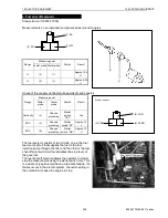
Fuel shut off solenoid
B
A
(6) 0.5BR
(4) 3WG
(5) 3BR
B-end coupler
Summary of Contents for EF-494T
Page 1: ...EF494T TM 06 2011 edition ...
Page 85: ...3 ENGINE 3 ENGINE EF494T TM 06 2011 edition 77 3 ENGINE ...
Page 88: ...3 ENGINE 3 ENGINE EF494T TM 06 2011 edition 80 B Return ...
Page 126: ...4 CLUTCH 4 CLUTCH EF494T TM 06 2011 edition 118 4 CLUTCH ...
Page 130: ...4 CLUTCH 4 CLUTCH EF494T TM 06 2011 edition 122 ...
Page 133: ...5 TRANSMISSION 5 TRANSMISSION EF494T TM 06 2011 edition 125 5 TRANMISSION ...
Page 167: ...7 FRONT AXLE 7 FRONT AXLE EF494T TM 06 2011 edition 159 7 FRONT AXLE ...
Page 169: ...7 FRONT AXLE 7 FRONT AXLE EF494T TM 06 2011 edition 161 7 2 CROSS SECTION VIEW ...
Page 176: ...8 POWER STEERING 8 POWER STEERING EF494T TM 06 2011 edition 168 8 POWER STEERING ...
Page 234: ...11 APPENDIXES 11 APPENDIXES EF494T TM 06 2011 edition 226 11 APPENDIXES ...
Page 235: ...11 APPENDIXES 11 APPENDIXES EF494T TM 06 2011 edition 227 11 1 HYDRAULIC CIRCUIT DIAGRAM ...
Page 236: ...228 11 2 ELECTRICAL CIRCUIT DIAGRAM 11 2 1 WIRING HARNESS ...
Page 238: ...230 11 2 3 ELECTRICAL WIRING DIAGRAM ...
Page 239: ......