3 ENGINE
3 ENGINE
EF494T TM 06/2011 edition
95
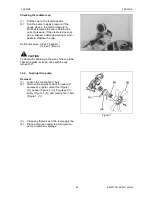
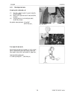
Checking the radiator cap
(1)
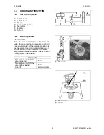
Put the cap on the tester adaptor.
(2)
Run the pump to apply pressure. If the
gauge stays in the normal range for 6
seconds it means the cap is holding the
correct pressure. If the pressure does not
go up, suspect a damaged spring or worn
gaskets. Replace the cap.
.
Normal pressure: 0.9 ±0.15 kgf/cm
2
(12.8±2.1 lb/sq.in)
CAUTION
To deal with variations in the size of the cap tabs,
check the pressure twice, once with the cap
turned 180°.
3.4.3 Fuel injection pump
Removal
(1)
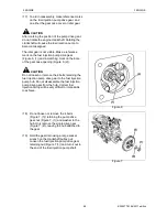
Loosen the cooling fan V-belt.
(2)
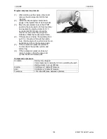
Remove the engine coolant fan guard (if
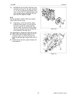
equipped), engine coolant fan (Figure 1,
(2)), spacer (Figure 1, (3)) if equipped, V-
pulley (Figure 1, (4)) and cooling fan V-belt
(Figure 1, (1)).
Figure 1
(3)
Close any fuel valves in the fuel supply line.
(4)
Place a drain pan under the fuel injection
pump to catch any spillage.
Summary of Contents for EF-494T
Page 1: ...EF494T TM 06 2011 edition ...
Page 85: ...3 ENGINE 3 ENGINE EF494T TM 06 2011 edition 77 3 ENGINE ...
Page 88: ...3 ENGINE 3 ENGINE EF494T TM 06 2011 edition 80 B Return ...
Page 126: ...4 CLUTCH 4 CLUTCH EF494T TM 06 2011 edition 118 4 CLUTCH ...
Page 130: ...4 CLUTCH 4 CLUTCH EF494T TM 06 2011 edition 122 ...
Page 133: ...5 TRANSMISSION 5 TRANSMISSION EF494T TM 06 2011 edition 125 5 TRANMISSION ...
Page 167: ...7 FRONT AXLE 7 FRONT AXLE EF494T TM 06 2011 edition 159 7 FRONT AXLE ...
Page 169: ...7 FRONT AXLE 7 FRONT AXLE EF494T TM 06 2011 edition 161 7 2 CROSS SECTION VIEW ...
Page 176: ...8 POWER STEERING 8 POWER STEERING EF494T TM 06 2011 edition 168 8 POWER STEERING ...
Page 234: ...11 APPENDIXES 11 APPENDIXES EF494T TM 06 2011 edition 226 11 APPENDIXES ...
Page 235: ...11 APPENDIXES 11 APPENDIXES EF494T TM 06 2011 edition 227 11 1 HYDRAULIC CIRCUIT DIAGRAM ...
Page 236: ...228 11 2 ELECTRICAL CIRCUIT DIAGRAM 11 2 1 WIRING HARNESS ...
Page 238: ...230 11 2 3 ELECTRICAL WIRING DIAGRAM ...
Page 239: ......

