6 REAR AXLE AND BRAKE
6 REAR AXLE AND BRAKE
EF494T TM 06/2011 edition
154
6.1.4 Brake
(1)
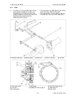
The brake is a wet type disk system. When
brake pedal is depressed, the brake rod
pulls brake lever to rotate cam lever that
rotates actuator. As the actuator rotates, the
balls farce the actuator toward the
differential carrier support.
This compresses the disks between the friction
plates and stops rotation of the shaft.
The parking brake is of the pedal lock system
and works the same way as the brake above.
(A) Parking brake lever
(B) Brake pedal
(C) Brake rod
(D) Cam shaft lever
(E) Actuator
(F) Cam lever shaft
(G) Actuator
(H) Friction plate
(I) Steel plate
(J) Differential carrier support
(K) Final drive pinion shaft
(L) Steel ball 9/16
(M) Cam shaft
Summary of Contents for EF-494T
Page 1: ...EF494T TM 06 2011 edition ...
Page 85: ...3 ENGINE 3 ENGINE EF494T TM 06 2011 edition 77 3 ENGINE ...
Page 88: ...3 ENGINE 3 ENGINE EF494T TM 06 2011 edition 80 B Return ...
Page 126: ...4 CLUTCH 4 CLUTCH EF494T TM 06 2011 edition 118 4 CLUTCH ...
Page 130: ...4 CLUTCH 4 CLUTCH EF494T TM 06 2011 edition 122 ...
Page 133: ...5 TRANSMISSION 5 TRANSMISSION EF494T TM 06 2011 edition 125 5 TRANMISSION ...
Page 167: ...7 FRONT AXLE 7 FRONT AXLE EF494T TM 06 2011 edition 159 7 FRONT AXLE ...
Page 169: ...7 FRONT AXLE 7 FRONT AXLE EF494T TM 06 2011 edition 161 7 2 CROSS SECTION VIEW ...
Page 176: ...8 POWER STEERING 8 POWER STEERING EF494T TM 06 2011 edition 168 8 POWER STEERING ...
Page 234: ...11 APPENDIXES 11 APPENDIXES EF494T TM 06 2011 edition 226 11 APPENDIXES ...
Page 235: ...11 APPENDIXES 11 APPENDIXES EF494T TM 06 2011 edition 227 11 1 HYDRAULIC CIRCUIT DIAGRAM ...
Page 236: ...228 11 2 ELECTRICAL CIRCUIT DIAGRAM 11 2 1 WIRING HARNESS ...
Page 238: ...230 11 2 3 ELECTRICAL WIRING DIAGRAM ...
Page 239: ......


