10 ELECTRIC EQUIPMENT
10 ELECTRIC EQUIPMENT
EF494T TM 06/2011 edition
214
10.2.3
Checkpoints of electrical equipment
2.
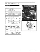
Alternator
Generator 40A: 119620-77201
The alternator has a built-in IC regulator. The alternating
current produced by the alternator is rectified into direct
current.
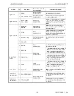
1. Do not reverse polarity between the IG and L terminals.
2. Do not make short-circuit between IG and L terminals.
3. Do not remove the battery terminals and the B terminal
when the alternator is running.
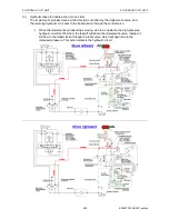
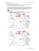
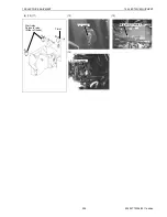
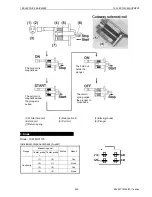
Check of alternator coupler without removing B terminal
With removal of IG and L terminal couplers
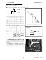
Instrument panel
Panel assy. Inst.: 1A7780-56502
When the key switch is turned to ON, charge lamp (1) turns
on. Turning the key switch further to SATRT, the engine
runs and the charge lamp turns off after a while.
(1) Charge lamp
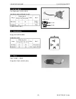
6. Key switch
See.
■
Electric equipment 10.1.1
“12. Key switch”..
Range
Measuring point
Status
Result
Tester probe
+
Tester probe
-
DCV
B
Chassis
grounding
Starter
switch
"OFF"
Approx. 12 V
Range
Measuring point
Status
Result
Tester probe
+
Tester probe
-
DCV
[1]
Chassis
grounding
Starter
switch "ON"
Approx. 12 V
DCV
[2]
Chassis
grounding
Starter
switch "ON"
Approx. 12 V
Wire side coupler
B terminal
IG and L
terminal
Summary of Contents for EF-494T
Page 1: ...EF494T TM 06 2011 edition ...
Page 85: ...3 ENGINE 3 ENGINE EF494T TM 06 2011 edition 77 3 ENGINE ...
Page 88: ...3 ENGINE 3 ENGINE EF494T TM 06 2011 edition 80 B Return ...
Page 126: ...4 CLUTCH 4 CLUTCH EF494T TM 06 2011 edition 118 4 CLUTCH ...
Page 130: ...4 CLUTCH 4 CLUTCH EF494T TM 06 2011 edition 122 ...
Page 133: ...5 TRANSMISSION 5 TRANSMISSION EF494T TM 06 2011 edition 125 5 TRANMISSION ...
Page 167: ...7 FRONT AXLE 7 FRONT AXLE EF494T TM 06 2011 edition 159 7 FRONT AXLE ...
Page 169: ...7 FRONT AXLE 7 FRONT AXLE EF494T TM 06 2011 edition 161 7 2 CROSS SECTION VIEW ...
Page 176: ...8 POWER STEERING 8 POWER STEERING EF494T TM 06 2011 edition 168 8 POWER STEERING ...
Page 234: ...11 APPENDIXES 11 APPENDIXES EF494T TM 06 2011 edition 226 11 APPENDIXES ...
Page 235: ...11 APPENDIXES 11 APPENDIXES EF494T TM 06 2011 edition 227 11 1 HYDRAULIC CIRCUIT DIAGRAM ...
Page 236: ...228 11 2 ELECTRICAL CIRCUIT DIAGRAM 11 2 1 WIRING HARNESS ...
Page 238: ...230 11 2 3 ELECTRICAL WIRING DIAGRAM ...
Page 239: ......

