3 ENGINE
3 ENGINE
EF494T TM 06/2011 edition
109
Engine compression pressure
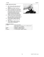
(1)
After warming up the engine, stop it and
remove the air cleaner and all the fuel
injectors.
(2)
Install the diesel engine compression
gauge in the injector hole of each cylinder.
(3)
Move the accelerator lever to the STOP
position (the zero position for fuel injection)
and operate the starting motor for 5-10
seconds (at 200-300 rpm). Read the
maximum value when the gauge has
stabilized. Make the measurement twice.
(4)
If the pressure is below the operating limit,
put 2 cc of engine oil through the nozzle
hole. Idle the engine for a while to let the oil
penetrate and check the pressure again.
(5)
If the compression pressure returns to
normal, check the cylinder, piston, and
piston ring.
(6)
If the compression pressure does not
return to normal, check the valve and
cylinder head and related parts.
Compression pressure
Condition
Battery fully charged
Valve clearance is normally 0.2 mm, permitting the self-
starting motor to run at 300 rpm.
Criteria
30-35 kg/cm
2
(426-497 lb/sq.in)
Limit
30-35 kg/cm
2
(426-497 lb/sq.in)
Tolerance
10% max difference between cylinders
Summary of Contents for EF-494T
Page 1: ...EF494T TM 06 2011 edition ...
Page 85: ...3 ENGINE 3 ENGINE EF494T TM 06 2011 edition 77 3 ENGINE ...
Page 88: ...3 ENGINE 3 ENGINE EF494T TM 06 2011 edition 80 B Return ...
Page 126: ...4 CLUTCH 4 CLUTCH EF494T TM 06 2011 edition 118 4 CLUTCH ...
Page 130: ...4 CLUTCH 4 CLUTCH EF494T TM 06 2011 edition 122 ...
Page 133: ...5 TRANSMISSION 5 TRANSMISSION EF494T TM 06 2011 edition 125 5 TRANMISSION ...
Page 167: ...7 FRONT AXLE 7 FRONT AXLE EF494T TM 06 2011 edition 159 7 FRONT AXLE ...
Page 169: ...7 FRONT AXLE 7 FRONT AXLE EF494T TM 06 2011 edition 161 7 2 CROSS SECTION VIEW ...
Page 176: ...8 POWER STEERING 8 POWER STEERING EF494T TM 06 2011 edition 168 8 POWER STEERING ...
Page 234: ...11 APPENDIXES 11 APPENDIXES EF494T TM 06 2011 edition 226 11 APPENDIXES ...
Page 235: ...11 APPENDIXES 11 APPENDIXES EF494T TM 06 2011 edition 227 11 1 HYDRAULIC CIRCUIT DIAGRAM ...
Page 236: ...228 11 2 ELECTRICAL CIRCUIT DIAGRAM 11 2 1 WIRING HARNESS ...
Page 238: ...230 11 2 3 ELECTRICAL WIRING DIAGRAM ...
Page 239: ......

