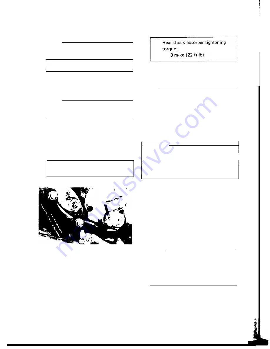
B. Swing arm removal
1. Remove nut on swing
tap out bolt with a
brass rod.
arm pivot bolt and
damping. There should be no noticeable
long aluminum or damping as shock extends.
NOTE:
Carefully remove the arm while noting the
location of spacing washers and shims.
Pivot bolt torque: 6.5 m-kg (47 ft-lb)
2. Tap out old bushing from each side of
pivot using the long rod.
3. Install new bushings using a press.
NOTE:
If tapping on bushing, bushing may be
broken.
C. Swing arm lubrication
1. Apply grease to grease fitting on top of
pivot with low pressure hand operated
gun. Apply until fresh grease appears at
both ends of pivot shaft.
Recommended lubricant:
Medium-weight grease
2. Wipe off excess grease.
1. Grease fitting
5-9. REAR SHOCK ABSORBER
A. Removal
Remove one (1) rear shock absorber at a time,
inspect and reinstall before removing the
other.
B. Inspection
1. Check the rod. If it is bent or damaged,
replace the shock absorber.
2. Check for oil leakage. If oil leakage is
evident, replace the shock absorber.
3. Operate shock absorber rod to check
4. Install the shock absorber on the machine.
Rear shock absorber tightening
5-10. CABLES AND FITTINGS
A.Cable maintenance
NOTE:
See maintenance and lubrication intervals
charts. Cable maintenance is primarily con-
cerned with preventing deterioration through
rust and weathering and providing proper
lubrication to allow the cable to move freely
within its housing. Cable removal is straight-
forward and uncomplicated. Removal will not
be discussed within this section.
WARNING:
Cable routing is very important. For details of
cable routing, see the table routing diagrams!
at the end of the manual. Improperly routed,
assembled or adjusted cables may make the
vehicle unsafe for operation.
1.
Remove the cable.
2. Check for free movement of cable within
its housing. If movement is obstructed,
check for fraying or kinking of cable
strands. If damage is evident, replace the
cable assembly.
3. To lubricate cable, hold in vertical posi-
tion. Apply lubricant to uppermost end of
cable. Leave in vertical position until
lubricant appears at bottom. Allow excess
to drain and reinstall.
NOTE:
Choice of lubricant depends upon con-
ditions and preferences. However, a semi-
drying chain and cable lubricant will
probably perform adequately under most
conditions.
B. Throttle maintenance
1. Remove Phillips head screws from throttle
housing assembly and separate two halves
of housing.
2. Disconnect cable end from throttle grip
48
assembly and remove grip assembly.
Summary of Contents for XS650 Series
Page 1: ......
Page 4: ...CHAPTER 1 GENERAL INFORMATION l l MACHINE IDENTIFICATION a 1 l 2 SPECIAL TOOLS ...
Page 39: ......
Page 45: ......
Page 55: ......
Page 76: ......
Page 77: ......
Page 78: ......
Page 79: ...XS650E Supplementary FOR XS650E MODELS AFTER ENGINE SERIAL NO 2FO 006501 ...
Page 84: ... _ _ _I __ l i _ _ I l R ...
Page 108: ......
Page 109: ......
Page 110: ......
Page 111: ......
Page 112: ......
Page 116: ...MAINTENANCE AND LUBRICATION CHART PERIODIC MAINTENANCE EMISSION CONTROL SYSTEM 3 ...
Page 117: ...t c c ...
Page 140: ......
Page 141: ...Supplementary ...
Page 149: ...2 Troubleshooting inspection ...
Page 150: ...LOW BEAM DOES NOT LlGHT WHEN HIGH BEAM IS DEFECTIVE ...
Page 161: ......
Page 162: ......
Page 163: ......
Page 164: ......
Page 165: ...Supplementary FOR XS650SE MODELS AFTER ENGINE SERIAL NUMBER 2FO 114241 ...
Page 174: ... R W wire to 118 ...
Page 175: ... 119 ...
Page 186: ......
Page 187: ......
Page 188: ......
Page 189: ......
Page 190: ......
Page 200: ...1 ...
Page 202: ...Torque Specifications A Nut ...
Page 212: ......
Page 213: ......
Page 214: ......
Page 215: ......


