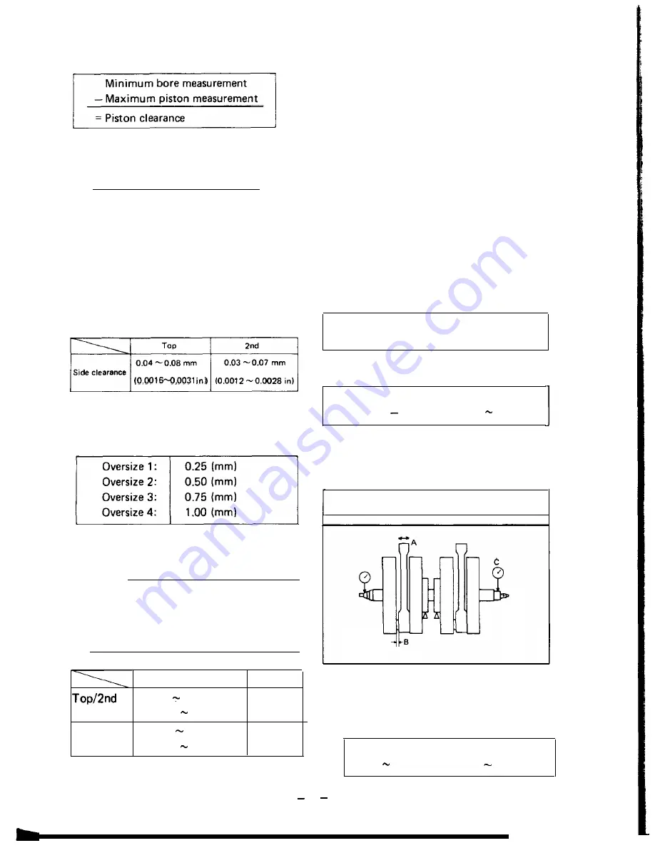
b. Determine piston clearance as follows:
Example:
75.02 mm
-74.97 mm
=0.05 mm piston clearance
c. Piston ring/ring groove fit must have
correct clearance. If the piston and ring
have already been used, the ring must be
removed and the ring groove cleaned of
carbon. The rings should then be rein
stalled. Use a feeler gauge to measure the
gap between the ring and the land.
1 0 . 0 0 1 2 - 0 . 0 0 2 8 i n )
2. Piston ring
a. The oversize top and middle ring sizes are
stamped on top of the ring.
b. Push the ring into the bore and check end
gap clearance with a feeler gauge.
NOTE:
The end gap on the expander spacer of
the oil control ring is unmeasureable. If
oil control ring rails show excessive gap,
all three components should be replaced.
Standard
Limit
0.2 0.4 mm
1.0 mm
ring
(0.0079 0.016 in)
(0.039 in)
Oil control
0.2 0.9 mm
Visual
(Rails)
(0.0079 0.0354 in) inspection
J. Piston pin
1.
2.
Apply a light film of oil to pin. install in
connecting rod small end. Check for play.
There should be no noticeable vertical
play. If play exists, check connecting rod
small end for wear. Replace pin and con-
necting rod as required.
The piston pin should have no noticeable
free play in piston. If the piston pin is
loose, replace the pin and/or the piston.
K. Crankshaft
1. Main bearing and big end bearing visually
inspect all friction surfaces for obvious
pits, scratches, chatter marks, or rust. Re-
place it if necessary.
2. Small end play(A)
Maximum allowable tolerance:
2.0 mm (0.079 in)
3.
Big end side clearance(B)
Standard clearance:
0.15 0.4 mm (0.0059 0.016 in)
4. Crankshaft run out(C)
Mount the crankshaft in V-blocks and
check for run out using a dial gauge.
Run out limit: 0.05 mm (0.002 in)
L. Oil pump
1. Check the clearance between housing and
outer rotor.
Standard clearance:
0.10 0.18 mm (0.0039 0.0071 in)
27
Summary of Contents for XS650 Series
Page 1: ......
Page 4: ...CHAPTER 1 GENERAL INFORMATION l l MACHINE IDENTIFICATION a 1 l 2 SPECIAL TOOLS ...
Page 39: ......
Page 45: ......
Page 55: ......
Page 76: ......
Page 77: ......
Page 78: ......
Page 79: ...XS650E Supplementary FOR XS650E MODELS AFTER ENGINE SERIAL NO 2FO 006501 ...
Page 84: ... _ _ _I __ l i _ _ I l R ...
Page 108: ......
Page 109: ......
Page 110: ......
Page 111: ......
Page 112: ......
Page 116: ...MAINTENANCE AND LUBRICATION CHART PERIODIC MAINTENANCE EMISSION CONTROL SYSTEM 3 ...
Page 117: ...t c c ...
Page 140: ......
Page 141: ...Supplementary ...
Page 149: ...2 Troubleshooting inspection ...
Page 150: ...LOW BEAM DOES NOT LlGHT WHEN HIGH BEAM IS DEFECTIVE ...
Page 161: ......
Page 162: ......
Page 163: ......
Page 164: ......
Page 165: ...Supplementary FOR XS650SE MODELS AFTER ENGINE SERIAL NUMBER 2FO 114241 ...
Page 174: ... R W wire to 118 ...
Page 175: ... 119 ...
Page 186: ......
Page 187: ......
Page 188: ......
Page 189: ......
Page 190: ......
Page 200: ...1 ...
Page 202: ...Torque Specifications A Nut ...
Page 212: ......
Page 213: ......
Page 214: ......
Page 215: ......


