CABLE ROUTING DIAGRAM
2-18
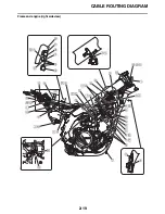
1. Clutch cable
2. Throttle cable (return)
3. Throttle cable (pull)
4. Cable holder
5. Intake air temperature sensor coupler (black)
6. Radiator hose
7. Rectifier/regulator
8. Rectifier/regulator lead
9. Rectifier/regulator coupler
10.Stator coil assembly lead
11.Battery band
12.Starter relay (blue tape)
13.Diode 5
14.Headlight relay (yellow tape)
15.Radiator fan motor fuse
16.Engine mounting bracket boss
17.Starter motor lead
18.Gear position switch lead
19.Lower engine bracket
20.Gear position switch coupler
21.Stator coil assembly coupler
22.Tension arm
23.Wire harness
24.Yamaha diagnostic tool coupler
25.Tank rail
26.Engine stop switch lead
27.Crankcase breather hose
28.Radiator
29.Radiator breather hose
30.Crankcase cover
31.Crankcase
32.Clamp
A. Pass the engine stop switch lead between the
frame and the cable holder.
B. Insert the Yamaha diagnostic tool coupler into
the connector, and fix it to the bracket.
C. Fasten the engine stop switch coupler to the
bracket of the inside.
D. Pass the rectifier/regulator lead (wire harness
side) to the inside of the tension arm (the side
of the vehicle).
E. Fasten the rectifier/regulator coupler to the
bracket. Attach the coupler cover.
F. Position the lock at the lower side of the vehi-
cle, cut the end of the plastic locking tie fac-
ing downward.
G. Place the diode outer than the starter relay
and the headlight relay.
H. Route the starter motor lead through the
inside of the engine mounting bracket boss,
and make sure it is located at the front side
instead of at the back end of the engine
mounting bracket boss.
I. Route the gear position switch lead along the
crankcase without slack.
J. Pass the gear position switch lead to the
inside of the lower engine bracket (the side of
the vehicle).
K. Pass the clutch cable with no downward sag
allowed.
L. Bring the protector of the clutch cable into
contact with the radiator hose, and pass it to
the outside of the gear position switch lead
and the stator coil assembly lead (the outside
of the vehicle).
M. No pinch is allowed the leads between the
radiator hose and the tension arm.
N. Pass the stator coil assembly lead through
back of the radiator. No pinch is allowed
between the radiator and the tension arm.
O. After connecting the gear position switch cou-
pler, attach the coupler cover.
P. After connecting the stator coil assembly cou-
pler, attach the coupler cover.
Q. Pass the wire harness to the front of the radi-
ator hose (the front of the vehicle), and to the
inside of the throttle cable (the side of the
vehicle).
R. Pass the engine stop switch lead between the
Yamaha diagnostic tool coupler and the tank
rail.
S. Route the crankcase breather hose between
the radiator and the frame. When doing so,
route it in front of the lower mounting boss of
the radiator.
T. Route the radiator breather hose between the
radiator hose and the crankcase breather
hose. Then route it between the down tubes.
U. Clamp the clutch cable at the front of the lead
(the front of the vehicle).
V. Insert the clip portion into the hole in the
frame. Fasten the locking portion so that it
faces toward the front of the vehicle, and then
cut off the excess end of the locking portion.
W. Insert the clamp into the hole in the cylinder
head.
When doing so, the starter motor lead should
not be twisted.
Summary of Contents for WR250FM 2021
Page 5: ...EAM20093 YAMAHA MOTOR CORPORATION U S A WR MOTORCYCLE LIMITED WARRANTY...
Page 8: ......
Page 10: ......
Page 52: ...MOTORCYCLE CARE AND STORAGE 1 40...
Page 62: ...ELECTRICAL SPECIFICATIONS 2 9 Radiator fan motor fuse 5 0 A Spare fuse 15 0 A...
Page 70: ...CABLE ROUTING DIAGRAM 2 17 EAM20152 CABLE ROUTING DIAGRAM Frame and engine left side view...
Page 72: ...CABLE ROUTING DIAGRAM 2 19 Frame and engine right side view...
Page 74: ...CABLE ROUTING DIAGRAM 2 21 Handlebar front view...
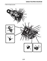
Page 76: ...CABLE ROUTING DIAGRAM 2 23 Frame and engine top view...
Page 78: ...CABLE ROUTING DIAGRAM 2 25 Frame and battery top view...
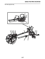
Page 80: ...CABLE ROUTING DIAGRAM 2 27 Rear brake right side view...
Page 82: ...CABLE ROUTING DIAGRAM 2 29 Front brake front view and right side view...
Page 84: ...CABLE ROUTING DIAGRAM 2 31 Taillight top view and right side view...
Page 86: ...CABLE ROUTING DIAGRAM 2 33...
Page 203: ...LUBRICATION SYSTEM CHART AND DIAGRAMS 5 3 1 Oil filter element 2 Oil pump...
Page 204: ...LUBRICATION SYSTEM CHART AND DIAGRAMS 5 4 1 Intake camshaft 2 Exhaust camshaft...
Page 278: ...TRANSMISSION 5 78...
Page 288: ...WATER PUMP 6 9...
Page 298: ...THROTTLE BODY 7 9...
Page 301: ......
Page 302: ...IGNITION SYSTEM 8 1 EAM20142 IGNITION SYSTEM EAM30277 CIRCUIT DIAGRAM...
Page 306: ...ELECTRIC STARTING SYSTEM 8 5 EAM20143 ELECTRIC STARTING SYSTEM EAM30279 CIRCUIT DIAGRAM...
Page 312: ...CHARGING SYSTEM 8 11 EAM20144 CHARGING SYSTEM EAM30282 CIRCUIT DIAGRAM...
Page 315: ...CHARGING SYSTEM 8 14...
Page 316: ...SIGNALING SYSTEM 8 15 EAM20154 SIGNALING SYSTEM EAM30348 CIRCUIT DIAGRAM...
Page 320: ...LIGHTING SYSTEM 8 19 EAM20153 LIGHTING SYSTEM EAM30346 CIRCUIT DIAGRAM...
Page 323: ...LIGHTING SYSTEM 8 22...
Page 324: ...COOLING SYSTEM 8 23 EAM20155 COOLING SYSTEM EAM30350 CIRCUIT DIAGRAM...
Page 327: ...COOLING SYSTEM 8 26...
Page 328: ...FUEL INJECTION SYSTEM 8 27 EAM20145 FUEL INJECTION SYSTEM EAM30284 CIRCUIT DIAGRAM...
Page 353: ...FUEL INJECTION SYSTEM 8 52...
Page 354: ...FUEL PUMP SYSTEM 8 53 EAM20146 FUEL PUMP SYSTEM EAM30287 CIRCUIT DIAGRAM...
Page 388: ...SELF DIAGNOSTIC FUNCTION AND DIAGNOSTIC CODE TABLE 9 15...
Page 398: ...CHASSIS 10 9...
Page 400: ......
Page 402: ......
Page 403: ...WR250FM 2021 WIRING DIAGRAM BAK 2819U 11_W D indd 1 2020 07 01 12 01 28...
Page 404: ...WR250FM 2021 WIRING DIAGRAM BAK 2819U 11_W D indd 2 2020 07 01 12 01 28...


