


CABLE ROUTING DIAGRAM
2-22
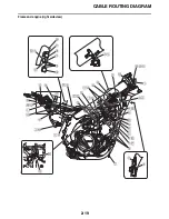
1. Clutch cable
2. Clutch switch lead
3. Engine stop switch lead
4. Front brake hose
5. Headlight lead
6. Warning light coupler
7. Start switch lead
8. Multi-function display coupler
9. Speed sensor coupler
10.Plastic locking tie
11.Speed sensor lead
12.Throttle cable
13.Multi-function display
14.Warning light lead
15.Warning light
A. Pass the throttle cable, clutch cable, clutch
switch lead, engine stop switch lead, start
switch lead and speed sensor lead between
the wire guide of the meter bracket and the
handle crown (in no particular order).
B. Pass the engine stop switch lead between the
frame and the cable guide.
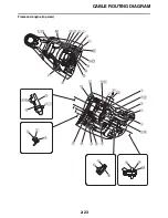
C. Fasten the wire harness, clutch switch lead,
start switch lead and speed sensor lead to
the meter bracket using the plastic locking tie.
When fastening, turn the steering to left and
no slack. The speed sensor lead should be
fastened at the gray tape. Face the end of the
plastic locking tie to the right side of the vehi-
cle. The excess should be cut.
D. Connect the headlight lead to the headlight.
E. After fastening the speed sensor lead, route it
as U-letter and route along the start switch
lead. Pass it through the bottom of the front
brake hose.
F. Fasten the start switch lead to the handlebar
using the plastic locking tie. Do not cut the
end of the plastic locking tie.
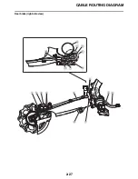
G. Vertical direction of vehicle
H. 70–110
I. Fasten the paint portion of the speed sensor
lead at the shrinking tube of the front brake
hose.
J. Fasten at the paint portion of the speed sen-
sor lead. The place of the front brake hose
does not matter.
K. Fasten the start switch lead and speed sen-
sor lead to the handlebar using the plastic
locking tie. Do not cut the end of the plastic
locking tie.
L. Fasten at the center of both sides of the
clamps.
M. Fasten the engine stop switch lead and the
clutch switch lead to the handlebar using the
plastic locking tie. Do not cut the end of the
plastic locking tie.
N. 30–50
Summary of Contents for WR250FM 2021
Page 5: ...EAM20093 YAMAHA MOTOR CORPORATION U S A WR MOTORCYCLE LIMITED WARRANTY...
Page 8: ......
Page 10: ......
Page 52: ...MOTORCYCLE CARE AND STORAGE 1 40...
Page 62: ...ELECTRICAL SPECIFICATIONS 2 9 Radiator fan motor fuse 5 0 A Spare fuse 15 0 A...
Page 70: ...CABLE ROUTING DIAGRAM 2 17 EAM20152 CABLE ROUTING DIAGRAM Frame and engine left side view...
Page 72: ...CABLE ROUTING DIAGRAM 2 19 Frame and engine right side view...
Page 74: ...CABLE ROUTING DIAGRAM 2 21 Handlebar front view...
Page 76: ...CABLE ROUTING DIAGRAM 2 23 Frame and engine top view...
Page 78: ...CABLE ROUTING DIAGRAM 2 25 Frame and battery top view...
Page 80: ...CABLE ROUTING DIAGRAM 2 27 Rear brake right side view...
Page 82: ...CABLE ROUTING DIAGRAM 2 29 Front brake front view and right side view...
Page 84: ...CABLE ROUTING DIAGRAM 2 31 Taillight top view and right side view...
Page 86: ...CABLE ROUTING DIAGRAM 2 33...
Page 203: ...LUBRICATION SYSTEM CHART AND DIAGRAMS 5 3 1 Oil filter element 2 Oil pump...
Page 204: ...LUBRICATION SYSTEM CHART AND DIAGRAMS 5 4 1 Intake camshaft 2 Exhaust camshaft...
Page 278: ...TRANSMISSION 5 78...
Page 288: ...WATER PUMP 6 9...
Page 298: ...THROTTLE BODY 7 9...
Page 301: ......
Page 302: ...IGNITION SYSTEM 8 1 EAM20142 IGNITION SYSTEM EAM30277 CIRCUIT DIAGRAM...
Page 306: ...ELECTRIC STARTING SYSTEM 8 5 EAM20143 ELECTRIC STARTING SYSTEM EAM30279 CIRCUIT DIAGRAM...
Page 312: ...CHARGING SYSTEM 8 11 EAM20144 CHARGING SYSTEM EAM30282 CIRCUIT DIAGRAM...
Page 315: ...CHARGING SYSTEM 8 14...
Page 316: ...SIGNALING SYSTEM 8 15 EAM20154 SIGNALING SYSTEM EAM30348 CIRCUIT DIAGRAM...
Page 320: ...LIGHTING SYSTEM 8 19 EAM20153 LIGHTING SYSTEM EAM30346 CIRCUIT DIAGRAM...
Page 323: ...LIGHTING SYSTEM 8 22...
Page 324: ...COOLING SYSTEM 8 23 EAM20155 COOLING SYSTEM EAM30350 CIRCUIT DIAGRAM...
Page 327: ...COOLING SYSTEM 8 26...
Page 328: ...FUEL INJECTION SYSTEM 8 27 EAM20145 FUEL INJECTION SYSTEM EAM30284 CIRCUIT DIAGRAM...
Page 353: ...FUEL INJECTION SYSTEM 8 52...
Page 354: ...FUEL PUMP SYSTEM 8 53 EAM20146 FUEL PUMP SYSTEM EAM30287 CIRCUIT DIAGRAM...
Page 388: ...SELF DIAGNOSTIC FUNCTION AND DIAGNOSTIC CODE TABLE 9 15...
Page 398: ...CHASSIS 10 9...
Page 400: ......
Page 402: ......
Page 403: ...WR250FM 2021 WIRING DIAGRAM BAK 2819U 11_W D indd 1 2020 07 01 12 01 28...
Page 404: ...WR250FM 2021 WIRING DIAGRAM BAK 2819U 11_W D indd 2 2020 07 01 12 01 28...