FUEL INJECTION SYSTEM
8-43
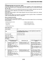
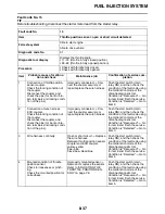
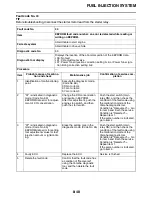
Fault code No. 33
3
Faulty ECU.
Execute the diagnostic mode.
(Code No. 08)
When the vehicle is upright:
0.4–1.4 (V)
When the vehicle is overturned:
3.7–4.4 (V)
Improper display
Replace the
ECU.
Service is finished.
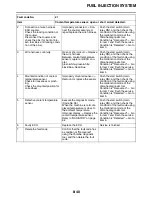
4
Delete the fault code.
Confirm that the fault code has
a condition of “Recovered”
using the Yamaha diagnostic
tool, and then delete the fault
code.
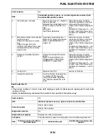
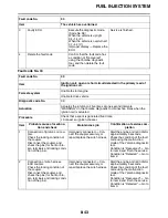
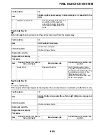
Fault code No.
33
Item
Ignition coil: open or short circuit detected in the primary lead of
the ignition coil.
Fail-safe system
Unable to start engine
Unable to drive vehicle
Diagnostic code No.
30
Actuation
Actuates the ignition coil five times at one-second intervals.
“WARNING” on the Yamaha diagnostic tool blinks five times when the
ignition coil is actuated.
Procedure
Check that a spark is generated five times.
•
Connect an ignition checker.
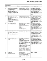
Item
Probable cause of malfunc-
tion and check
Maintenance job
Confirmation of service com-
pletion
1
Connection of ignition coil cou-
pler.
Check the locking condition of
the coupler.
Disconnect the coupler, and
check the pins (for bent or bro-
ken terminals and locking condi-
tion of the pins).
Improperly connected
Con-
nect the coupler securely, or
repair/replace the wire harness.
Start the engine and let it idle for
approximately 5 seconds.
Check the condition of the fault
code using the malfunction
mode of the Yamaha diagnostic
tool.
Condition is “Recovered”
Go
to item 8 and finish the service.
Condition is “Detected”
Go to
item 2.
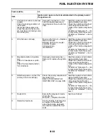
2
Connection of wire harness
ECU coupler.
Check the locking condition of
the coupler.
Disconnect the coupler, and
check the pins (for bent or bro-
ken terminals and locking condi-
tion of the pins).
Improperly connected
Con-
nect the coupler securely, or
repair/replace the wire harness.
Start the engine and let it idle for
approximately 5 seconds.
Check the condition of the fault
code using the malfunction
mode of the Yamaha diagnostic
tool.
Condition is “Recovered”
Go
to item 8 and finish the service.
Condition is “Detected”
Go to
item 3.
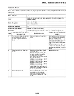
Fault code No.
30
Item
The vehicle has overturned.
Summary of Contents for WR250F 2022
Page 5: ...EAM20093 YAMAHA MOTOR CORPORATION U S A WR MOTORCYCLE LIMITED WARRANTY...
Page 8: ......
Page 10: ......
Page 41: ...MULTI FUNCTION DISPLAY 1 29...
Page 62: ...ELECTRICAL SPECIFICATIONS 2 9 Radiator fan motor fuse 5 0 A Spare fuse 15 0 A...
Page 70: ...CABLE ROUTING DIAGRAM 2 17 EAM20152 CABLE ROUTING DIAGRAM Frame and engine left side view...
Page 72: ...CABLE ROUTING DIAGRAM 2 19 Frame and engine right side view...
Page 74: ...CABLE ROUTING DIAGRAM 2 21 Handlebar front view...
Page 76: ...CABLE ROUTING DIAGRAM 2 23 Frame and engine top view...
Page 78: ...CABLE ROUTING DIAGRAM 2 25 Frame and battery top view...
Page 80: ...CABLE ROUTING DIAGRAM 2 27 Rear brake right side view...
Page 82: ...CABLE ROUTING DIAGRAM 2 29 Front brake front view and right side view...
Page 84: ...CABLE ROUTING DIAGRAM 2 31 Taillight top view and right side view...
Page 86: ...CABLE ROUTING DIAGRAM 2 33...
Page 204: ...LUBRICATION SYSTEM CHART AND DIAGRAMS 5 3 1 Oil filter element 2 Oil pump...
Page 205: ...LUBRICATION SYSTEM CHART AND DIAGRAMS 5 4 1 Intake camshaft 2 Exhaust camshaft...
Page 278: ...TRANSMISSION 5 77...
Page 288: ...WATER PUMP 6 9...
Page 298: ...THROTTLE BODY 7 9...
Page 301: ......
Page 302: ...IGNITION SYSTEM 8 1 EAM20142 IGNITION SYSTEM EAM30277 CIRCUIT DIAGRAM...
Page 306: ...ELECTRIC STARTING SYSTEM 8 5 EAM20143 ELECTRIC STARTING SYSTEM EAM30279 CIRCUIT DIAGRAM...
Page 312: ...CHARGING SYSTEM 8 11 EAM20144 CHARGING SYSTEM EAM30282 CIRCUIT DIAGRAM...
Page 315: ...CHARGING SYSTEM 8 14...
Page 316: ...SIGNALING SYSTEM 8 15 EAM20154 SIGNALING SYSTEM EAM30348 CIRCUIT DIAGRAM...
Page 320: ...LIGHTING SYSTEM 8 19 EAM20153 LIGHTING SYSTEM EAM30346 CIRCUIT DIAGRAM...
Page 323: ...LIGHTING SYSTEM 8 22...
Page 324: ...COOLING SYSTEM 8 23 EAM20155 COOLING SYSTEM EAM30350 CIRCUIT DIAGRAM...
Page 327: ...COOLING SYSTEM 8 26...
Page 328: ...FUEL INJECTION SYSTEM 8 27 EAM20145 FUEL INJECTION SYSTEM EAM30284 CIRCUIT DIAGRAM...
Page 353: ...FUEL INJECTION SYSTEM 8 52...
Page 354: ...FUEL PUMP SYSTEM 8 53 EAM20146 FUEL PUMP SYSTEM EAM30287 CIRCUIT DIAGRAM...
Page 388: ...SELF DIAGNOSTIC FUNCTION AND DIAGNOSTIC CODE TABLE 9 15...
Page 398: ...CHASSIS 10 9...
Page 400: ......
Page 402: ......

