Toolbar
Reference Manual
TF Series
- 21 -
8
Log icon (
)
Displays the LOG screen.
9
About icon (
)
Displays the ABOUT screen.
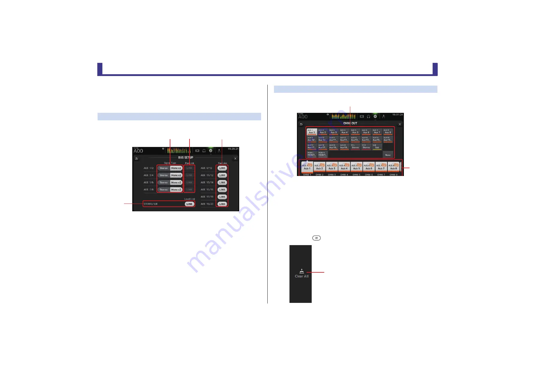
BUS SETUP screen
Allows you to configure bus settings. You can change basic settings such as stereo/mono, Pan
Link, etc. These settings are included when saving a Scene.
1
AUX1/2–AUX7/8 signal type buttons
Determines how each pair of buses is processed. You can set each pair to be either
Stereo (an odd and even numbered bus are paired and main parameters are shared
between the two) or MONO x2 (two independent mono channels).
2
AUX1/2–AUX7/8 Pan Link buttons
Turns pan link on and off for AUX1/2–AUX7/8.
These buttons are only displayed if the Signal Type of the corresponding bus is set to
Stereo. When these buttons are turned on, the pan setting of signals sent from input
channels to the corresponding two buses will link with the Stereo bus pan setting.
3
AUX9/10–AUX19/20 Pan Link buttons
Turns pan link on and off for AUX9/10–AUX19/20.
4
STEREO/SUB LINK (V1.1 and later)
When turned on, the levels of the STEREO channel and the SUB channel are linked.
OMNI OUT screen
Allows you to configure the output channels that are sent to the OMNI OUT jacks.
1
OMNI OUT1–16 buttons
Allows you to select which OMNI OUT jack will be configured.
The name of the channel currently assigned to each OMNI OUT jack is also displayed in
the buttons.
2
Output channel buttons
Determines which output channel or monitor output will be assigned to the OMNI OUT
jack you selected for
1
. If you select None, nothing will be output to the corresponding
OMNI OUT jack.
OMNI OUT screen menu
Press the Menu key (
) from the OMNI OUT screen to display the following items.
ձ
ղ
ճ
մ
1
Clear All icon
Clears all assignments for each OMNI OUT jack (all
will be set to None).
ղ
ձ
ձ


