21
STAGEPAS 600i
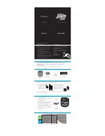
Fig.B-11
(図B-11)
Photo B-1
(写真B-1)
MIX62
MIXER PANEL 6 ASSEMBLY
(MIXパネル6組立)
SHIELD MIX 6 ASSEMBLY
(シールドMIX6組立)
Panel side
(パネル面)
[540]
[560]
[560]
[570]
[580]
[580]
[590]
[570]
[A]
[B]
[540]
[550A]
[150]
[550B]
[550B]
[550B]
MIXER PANEL 6 ASSEMBLY
(MIXパネル6組立)
B-9-7-3 Lift the shield mix 6 assembly in the direction of the
arrow as shown in Photo B-1, and remove the
fi
ve (5)
screws marked [130] and four (4) hexagonal spacers
marked [140]. The MIX62 circuit board can then be
removed. (Fig. B-10, Photo B-1)
*
The below parts are not components of the MIX62
circuit board. When replacing the MIX62 circuit board,
remove the below parts from the MIX62 circuit board
and install them to the new circuit board. (Fig. B-11)
[550B] : PUSH BUTTON HPF
6 pcs
[560] : VOLUME KNOB SMALL
(WHITE/BLACK)
8
pcs
[570] : VOLUME KNOB SMALL
(GREEN/BLACK) 22
pcs
[580] : VOLUME KNOB SMALL
(BLUE/BLACK)
5
pcs
[590] : VOLUME KNOB SMALL
(RED/BLACK)
1
pc
*
When installing the MIX62 circuit board, tighten the
five (5) screws marked [130] and then the four (4)
hexagonal spacers marked [140].
First tighten the two (2) priority screws in order as
shown in Fig. B-10.
B-9-7-3 シールド MIX6 組立を写真 B-1 のように矢印の方
向へめくり、[130] のネジ 5 本と [140] の 6 角スペー
サーを 4 本外して、MIX62 シートを外します。
(図 B-10、写真 B-1)
※
下記の部品は、MIX62 シートの構成部品ではありません。
MIX62 シートを交換する際には、MIX62 シートから下
記の部品を取り外して、新しいシートに取り付けてくだ
さい。(図 B-11)
[550B] : ボタン HPF
6 個
[560] : ノブ VR 小(白/黒)
8 個
[570] : ノブ VR 小(緑/黒)
22 個
[580] : ノブ VR 小(青/黒)
5 個
[590] : ノブ VR 小(赤/黒)
1 個
※
MIX62 シートを取り付けるときには、[130] のネジ 5 本
を締めてから [140] の 6 角スペーサー 4 本を締めてくだ
さい。
このとき、優先ネジ 2 本を図に示す順で先に締めてくだ
さい。(図 B-10)


