QL5/QL1
117
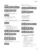
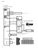
C. PHANTOM VOLTAGE (INPUT 1)
With No.2 and No.3 pins of XLR shorted and 10 k
Ω
load
connected between No.2 and No.1 pins, check that the voltage
is as follows when the +48 key is turned on.
Also, check that discharging starts immediately when the +48
key is turned off.
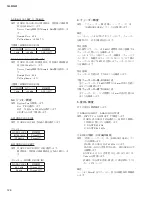
2-2. QL5: INPUT 17-32
→
OMNI OUT 1-16
QL1: INPUT 9-16
→
OMNI OUT 1-8
Parameters:
QL5: Input the analog signal from INPUT (XLR) of CH 17-32
and measure the signal output from OUTPUT of CH 17-32.
Assign OMNI IN CH 17-32 to OMNI OUT 1-16.
QL1: Input the analog signal from INPUT (XLR) of CH 9-16
and measure the signal output from OUTPUT of CH 9-16.
Assign OMNI IN CH 9-16 to OMNI OUT 1-8.
A. GAIN MIN
1
Gain
2
Distortion
3
Noise level
Parameters: Short the CH IN to be measured with 150
Ω
.
4
QL5:
CH 17‒32/QL1: CH 9‒16
level difference
Con
fi
rm the range of difference in the gain measured in item
1
above as follows.
5
Crosstalk between adjacent channels
Parameters: Turn on OMNI OUT of only one odd number
channel for output, turn off OMNI OUT of other
channels and measure the noise level of even
number channels next to the odd number channel
on both sides.
Short INPUT of the even number channels to be
measured with 150
Ω
.
Perform the same check on the even number channels.
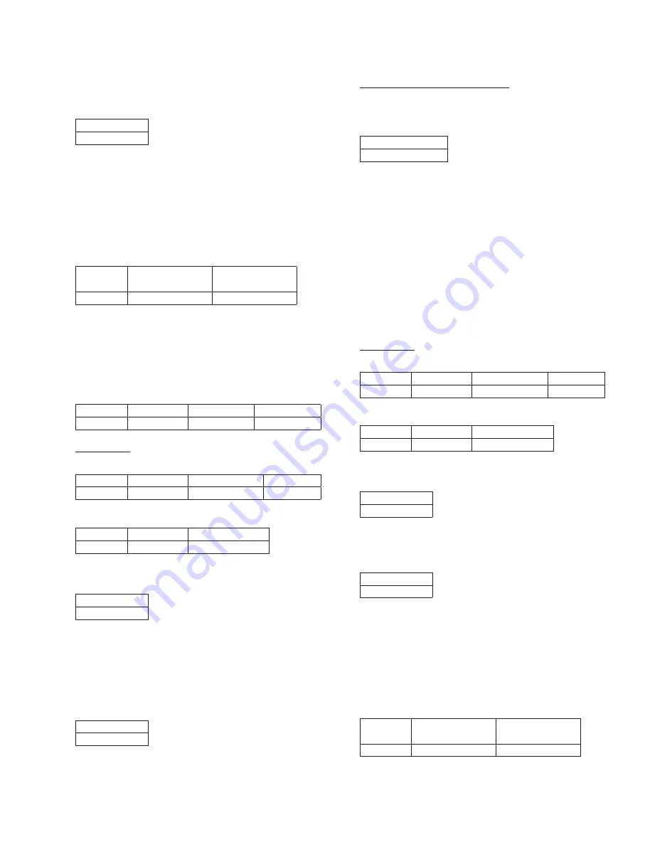
Input Frequency
Input Level
Prescribed Output Level Permissible Range
1 kHz
+10 dBu
+4 dBu
+4±2 dBu
Input Frequency
Output Level
Permissible Range
1 kHz
+22 dBu
0.01 % or below
Permissible Range
–80 dBu or below
5
QL5:
CH 1‒16/QL1: CH 1‒8
level difference
Confirm the range of difference in the gain measured in
item
1
above as follows.
6
Crosstalk between adjacent channels
Parameters: Turn on OMNI OUT of only one odd number
channel for output, turn off OMNI OUT of other
channels and measure the noise level of even
number channels next to the odd number channel
on both sides.
Short INPUT of the even number channels to be
measured with 150
Ω
.
Perform the same check on the even number channels.
7
Maximum output
(QL5: OMNI OUT 1–16 / QL1: OMNI OUT 1–8)
Parameters: Assign only the built-in oscillator to OMNI OUT
1-16 (in case of QL5) or OMNI OUT 1-8 (in case
of QL1).
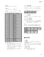
B. GAIN MIN
1
Gain (QL5: INPUT 1–16 / QL1: INPUT 1–8)
2
Distortion (QL5: INPUT 1–16 / QL1: INPUT 1–8)
3
Noise level EIN (QL5: INPUT 1–16 / QL1: INPUT 1–8)
Parameters: Short the CH IN to be measured with 150
Ω
.
If the measured value is out of the above permissible
range,con
fi
rm that “measured value – (Gain at 1kHz)
≦
-128”
is obtained.
4
Level difference (QL5:
CH 1‒16 / QL1: CH 1‒8
)
Confirm the range of difference in the gain measured in
item
1
above as follows.
Input Frequency
Output Level
Permissible Range
Permissible Range(Distortion)
1 kHz
+24 dBu
+24±0.5 dBu
0.01 % or below
Input Frequency
Input Level
Prescribed Output Level Permissible Range
1 kHz
–62 dBu
+4 dBu
+4±2 dBu
Input Frequency
Output Level
Permissible Range
1 kHz
+22 dBu
0.02 % or below
Permissible Range
Within 2 dB
Permissible Range
–62 dBu or below
Permissible Range
Within 1 dB
Permissible Range
Within 1 dB
Input Frequency
Output Level
(Odd Channel)
Permissible Range
(Even Channel)
1 kHz
+23 dBu
‒57 dBu
or below
Input Frequency
Output Level
(Odd Channel)
Permissible Range
(Even Channel)
1 kHz
+23 dBu
‒57 dBu
or below
Permissible Range
DC 33.6 V — 36.1 V
Summary of Contents for QL5
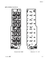
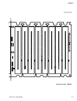
Page 3: ...103 QL5 QL1 PNL PNCOM Circuit Board 2NA ZF60470 1 WR 31 0 1 Component side Pattern side...
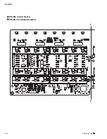
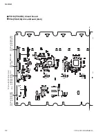
Page 4: ...QL5 QL1 104 2NA ZF60450 1 PN16M Circuit Board PN16S Circuit Board QL5 F F...
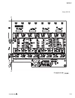
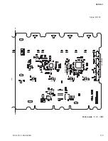
Page 5: ...105 QL5 QL1 Component side 2NA ZF60450 1 Scale 90 100 F F...
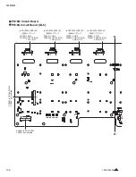
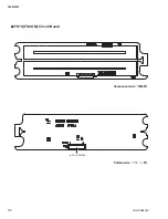
Page 8: ...QL5 QL1 108 PNR PNCOM Circuit Board 2NA ZF60470 1 Component side...
Page 9: ...109 QL5 QL1 PNR PNCOM Circuit Board 2NA ZF60470 1 WR 31 0 1 WR 31 0 1 Pattern side...
Page 10: ...QL5 QL1 110 FD1M FDCOM Circuit Board FD2 FDCOM Circuit Board QL5 FD1M FD2 2NA ZK68030 H H...
Page 11: ...111 QL5 QL1 FD1M FD2 2NA ZK68030 H H Component side Scale 90 100...
Page 13: ...113 QL5 QL1 Pattern side Scale 90 100 not installed I I FD1M FD2 2NA ZK68030...
Page 14: ...QL5 QL1 114 Pattern side Component side FD1S FDCOM Circuit Board WR 6 1 2NA ZK68030...
Page 50: ...QL5 QL1 150 2 H 3 O X O 4 BOX 5x4 1 18 LCD Test LCD LCD 1 3 2 9 5 OK NG 1...
Page 69: ...QL5 QL1 169 5 Start QL OK Status Updating 1 1 6 OK Status Update Done 7 Status Error QL...
Page 73: ...QL5 QL1 173 CD CD Ctrl Audio CD wav OK 01 01 Ctrl P 8 8 8 8 m ON ON OVER 10 00 dB 0 00 dB...
Page 89: ...QL5 QL1 189 q w NG OK...
Page 91: ...QL5 QL1 191 y u i o F1 F12 0 Port Setting error Ethernet Network...

