QL5/QL1
138
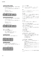
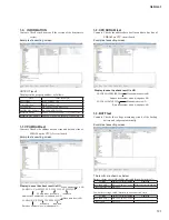
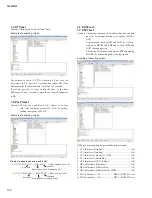
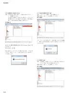
1-21. DNT Brooklyn2 Test
Contents Determines whether the correct Brooklyn2 module is
installed for each model and also checks whether the
Brooklyn2 audio signal and Ethernet connection are
satisfactory or not.
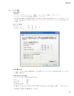
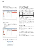
Example of executing screen
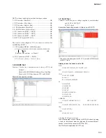
1-22. DNT SIO Test
Contents Checks the connection between DSP7 and DANTE
by transmitting and receiving signals.
Checks the condition of DNT circuit board
and Brooklyn2 by executing UART and SPI
communication between them.
Checks visually each of Primary and Secondary
LEDs for lighting(
fl
ashing).
Example of executing screen
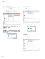
Enter the results of the LED light up (
fl
ash) check in the
dialog box below.
2. Tests not requiring PC application
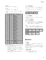
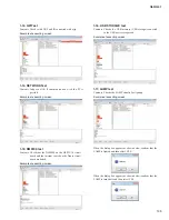
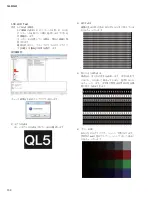
2-0. CN NAME LCD Display Test
After starting, at the same time as the check mode is activated,
the back light of all Mini LCDs lights up and the check pattern
appears.
As the check pattern changes at every pressing of any switch,
check visually that there is nothing abnormal.
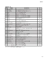
The table below shows the contents to be checked for each
check pattern.
Also, check for reversed contrast as described below during the
normal operation check or sound output check.
While viewing the NAME DISPLAY at the height barely
visible from the front pad, adjust the contrast (close to the
maximum) so that the display looks deep black. If it doesn’t
become deep black in that state but the NAME DISPLAY
viewed at the height barely visible from the opposite (rear)
side looks deep black, it is judged as NG because the angle of
visibility is reversed.
2-1. All LEDs Lighting Test
Press any 3 switches simultaneously in the CH NAME LCD
display check mode, and the All LEDs Lighting Test mode will
be activated.
Con
fi
rm visually that all LEDs on the panel are turned on.
2-2. Respective Color LEDs Lighting Test
Press any 3 switches simultaneously in the All LEDs Lighting
Test mode, and the Respective Color LEDs Lighting Test mode
will be activated.
Every time any one switch is pressed, the lighting LEDs change
in the order of red, orange and green.
Check visually that there is no LED lit in any different color.
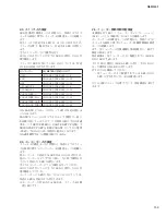
All dot lighting
All dots should be turned on.
Frame lighting
Outermost dots should light in the frame shape.
All dots turned off All dots should be turned off.
CH number display
Numbers should be displayed in order from the
left.
Summary of Contents for QL5
Page 3: ...103 QL5 QL1 PNL PNCOM Circuit Board 2NA ZF60470 1 WR 31 0 1 Component side Pattern side...
Page 4: ...QL5 QL1 104 2NA ZF60450 1 PN16M Circuit Board PN16S Circuit Board QL5 F F...
Page 5: ...105 QL5 QL1 Component side 2NA ZF60450 1 Scale 90 100 F F...
Page 8: ...QL5 QL1 108 PNR PNCOM Circuit Board 2NA ZF60470 1 Component side...
Page 9: ...109 QL5 QL1 PNR PNCOM Circuit Board 2NA ZF60470 1 WR 31 0 1 WR 31 0 1 Pattern side...
Page 10: ...QL5 QL1 110 FD1M FDCOM Circuit Board FD2 FDCOM Circuit Board QL5 FD1M FD2 2NA ZK68030 H H...
Page 11: ...111 QL5 QL1 FD1M FD2 2NA ZK68030 H H Component side Scale 90 100...
Page 13: ...113 QL5 QL1 Pattern side Scale 90 100 not installed I I FD1M FD2 2NA ZK68030...
Page 14: ...QL5 QL1 114 Pattern side Component side FD1S FDCOM Circuit Board WR 6 1 2NA ZK68030...
Page 50: ...QL5 QL1 150 2 H 3 O X O 4 BOX 5x4 1 18 LCD Test LCD LCD 1 3 2 9 5 OK NG 1...
Page 69: ...QL5 QL1 169 5 Start QL OK Status Updating 1 1 6 OK Status Update Done 7 Status Error QL...
Page 73: ...QL5 QL1 173 CD CD Ctrl Audio CD wav OK 01 01 Ctrl P 8 8 8 8 m ON ON OVER 10 00 dB 0 00 dB...
Page 89: ...QL5 QL1 189 q w NG OK...
Page 91: ...QL5 QL1 191 y u i o F1 F12 0 Port Setting error Ethernet Network...

