QL5/QL1
154
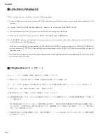
FIRMWARE のアップデート
* Make sure that the power should never be turned off during updating.
1) Prepare a USB memory and the environment (PC with USB connector) with which the data can be written to and read from the USB
memory.
2) Copy the “MQLPx_xx.PGM”
fi
le in the Updata (QL_Updata) to the root directory of the USB STORAGE.
3) Insert the USB memory to the USB connector of the QL itself and turn on the power switch.
4) When the con
fi
rmation message to execute the UPDATE is displayed, touch the
[OK]
button.
5) As PROGRESS advances and is
fi
nished, the main program is activated automatically. After con
fi
rming that, turn off the power
switch and disconnect the USB memory.
If the power is turned on again after updating the PROGRAM, the INITIALIZE screen may appear by a CHECK SUM ERROR. In
that case, execute ALL INITIALIZE. Wait until the normal screen appears and the USB ACCESS indicator turns off and then turn off
the power switch.
* The version may not appear in the SETUP screen when the screen is changed to the normal screen immediately after UPDATE. In this
case, switch on the power again.
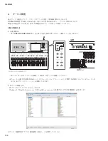
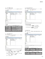
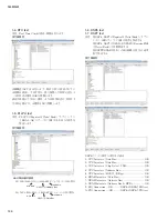
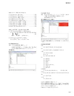
UPDATING FIRMWARE
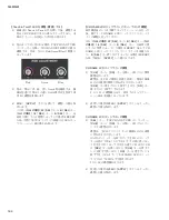
※ バージョンアップ中は絶対に電源が切れないように配慮してください。
1) USBメモリーとそれを読み書きできる環境(USB端子を搭載したPC)を準備します。
2) アップデータ(QL̲Updata)の中のMQLPx̲xx.PGMファイルをUSB STORAGEのルートディレクトリにCOPYします。
3) USBメモリーをQL 本体のUSB 端子に挿し、電源を入れます。
4) UPDATEをしていいか聞いてくるので、
[OK]
ボタンをタッチします。
5) PROGRESSが進んでいき、完了すると自動的に本体プログラムが起動するので、これを確認後電源を切ってUSBメモ
リーを抜きます。
なおPROGRAMのアップデートを行って再度電源を入れ直すと、CHECK SUM ERRORでINITIALIZEの画面が出るこ
とがあります。その場合ALL INITIALIZEを行います。通常画面になってUSB のACCESSインジケーターが消えるま
で待ってから電源を落とします。
* UPDATE後にそのまま通常画面にすると、SETUP画面でバージョンが表示されないことがあります。その場合は電源
を入れ直してください。
Summary of Contents for QL5
Page 3: ...103 QL5 QL1 PNL PNCOM Circuit Board 2NA ZF60470 1 WR 31 0 1 Component side Pattern side...
Page 4: ...QL5 QL1 104 2NA ZF60450 1 PN16M Circuit Board PN16S Circuit Board QL5 F F...
Page 5: ...105 QL5 QL1 Component side 2NA ZF60450 1 Scale 90 100 F F...
Page 8: ...QL5 QL1 108 PNR PNCOM Circuit Board 2NA ZF60470 1 Component side...
Page 9: ...109 QL5 QL1 PNR PNCOM Circuit Board 2NA ZF60470 1 WR 31 0 1 WR 31 0 1 Pattern side...
Page 10: ...QL5 QL1 110 FD1M FDCOM Circuit Board FD2 FDCOM Circuit Board QL5 FD1M FD2 2NA ZK68030 H H...
Page 11: ...111 QL5 QL1 FD1M FD2 2NA ZK68030 H H Component side Scale 90 100...
Page 13: ...113 QL5 QL1 Pattern side Scale 90 100 not installed I I FD1M FD2 2NA ZK68030...
Page 14: ...QL5 QL1 114 Pattern side Component side FD1S FDCOM Circuit Board WR 6 1 2NA ZK68030...
Page 50: ...QL5 QL1 150 2 H 3 O X O 4 BOX 5x4 1 18 LCD Test LCD LCD 1 3 2 9 5 OK NG 1...
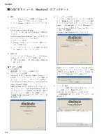
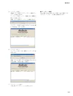
Page 69: ...QL5 QL1 169 5 Start QL OK Status Updating 1 1 6 OK Status Update Done 7 Status Error QL...
Page 73: ...QL5 QL1 173 CD CD Ctrl Audio CD wav OK 01 01 Ctrl P 8 8 8 8 m ON ON OVER 10 00 dB 0 00 dB...
Page 89: ...QL5 QL1 189 q w NG OK...
Page 91: ...QL5 QL1 191 y u i o F1 F12 0 Port Setting error Ethernet Network...

