b. Lift the other end from the hole and remove
the retaining wire from the clutch hub.
c. Remove clutch plate No. 1 (B,
Figure 21
), the
clutch boss spring and the plate seat from the
clutch hub.
Installation
1. Assemble the clutch boss damper assembly, if it
was removed, as follows:
a. Install the plate seat onto the clutch hub and
then install the clutch boss spring.
b. Install clutch plate No. 1 (B,
Figure 21
) onto
the clutch boss.
c. Seat one end of the retaining wire through the
hole in the clutch boss.
d. Press the retaining wire into the grooves
around the circumference of the clutch boss,
then insert the remaining end of the retaining
wire into the hole (A,
Figure 21
).
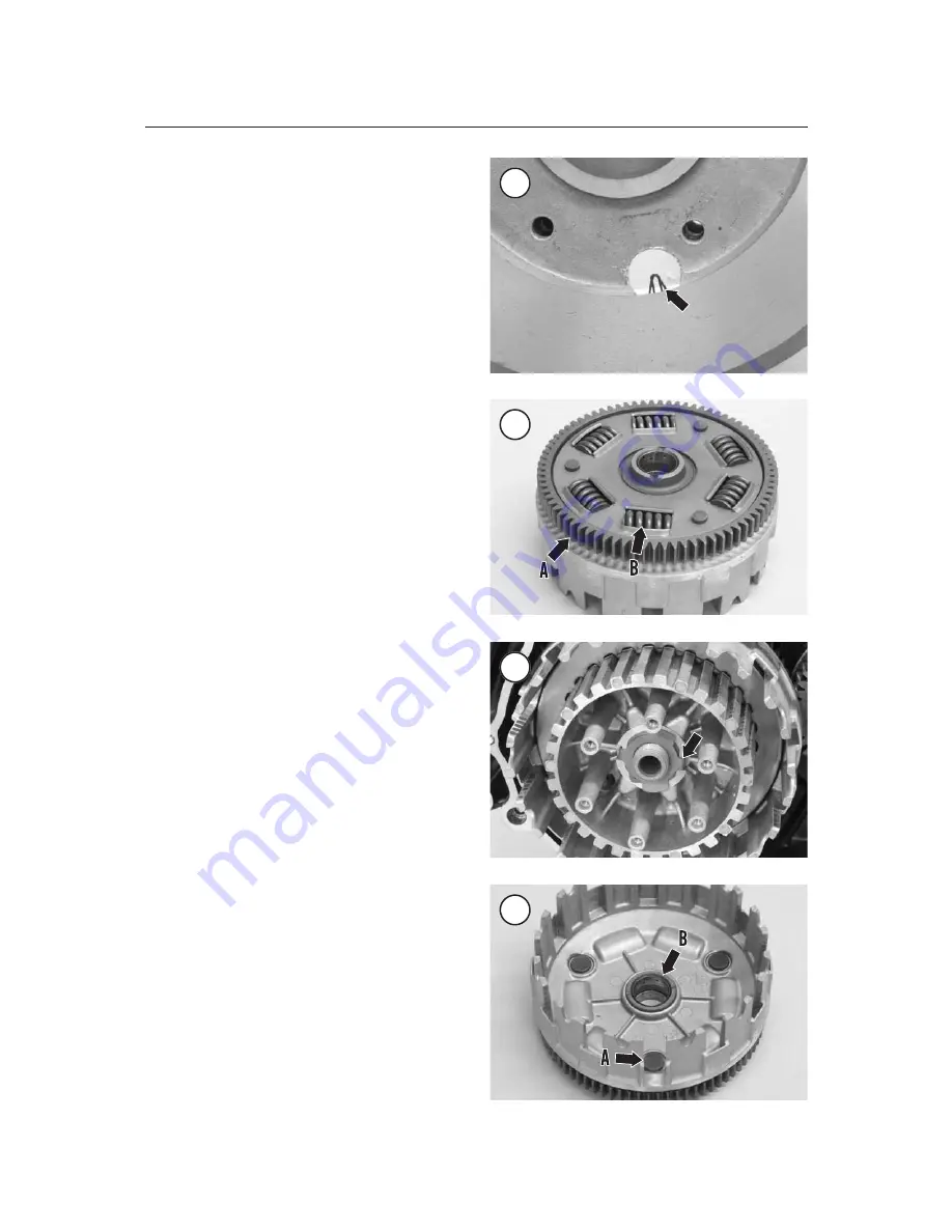
e. Make sure both ends of the retaining wire are
locked in the clutch boss hole (
Figure 22
).
2. Install the clutch housing onto the mainshaft as
follows:
a. Apply oil to the bushing in the clutch housing
hub.
b. Slide the clutch housing (B,
Figure 20
) onto
the mainshaft until the teeth of the primary
driven gear (A,
Figure 23
) on the housing en-
gage the teeth of the primary drive gear (C,
Figure 20
). Gently push the clutch housing
onto the mainshaft until it bottoms.
3. Install the thrust washer (A,
Figure 20
) onto the
mainshaft.
4. Slide the clutch boss (
Figure 19
) onto the
mainshaft.
5. Install a new lockwasher so its arms (
Figure 24
)
engage the cutouts in the clutch boss.
6. Turn the clutch nut (B,
Figure 16
) onto the
mainshaft. The concave side of the nut must face in
toward the lockwasher.
7. Use the same tool set-up used during removal to
hold the clutch boss (
Figure 17
) in place, and
torque the clutch nut to 70 N•m (52 ft.-lb.).
8. Bend each lockwasher ear (A,
Figure 16
) flat
against the nut.
NOTE
Apply fresh engine oil to each friction
disc to avoid clutch lock up. Install
each friction disc so the tab with the
174
CHAPTER SIX
22
23
24
25


