


PERIODIC MAINTENANCE
3-7
Example:
1.775 mm (0.06988 in) + 0.07 mm (0.0028 in)
= 1.845 mm (0.07264 in)
The valve pad number is 185.
d. Install a new valve pad “1” and the valve lifter
“2”.
TIP
• Lubricate the valve lifter with engine oil.
• Install the valve lifter and the valve pad in the
correct place.
• The valve lifter must turn smoothly when rotat-
ed by hand.
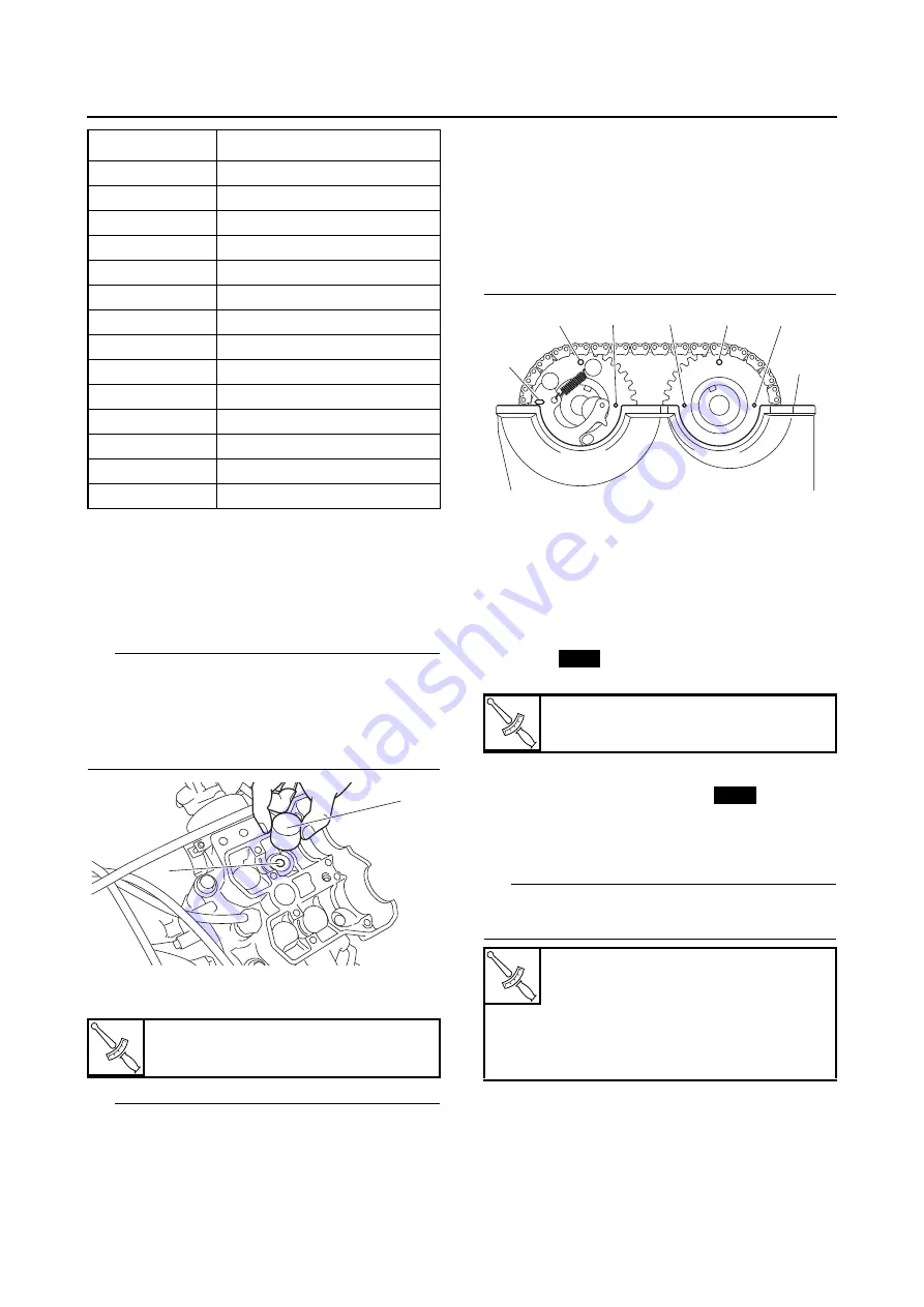
e. Install the exhaust and intake camshafts, tim-
ing chain and camshaft caps.
TIP
• Refer to “CAMSHAFTS” on page 5-12.
• Lubricate the camshaft lobes and camshaft
journals with engine oil.
• Position the holes “a” in the intake camshaft
sprocket and exhaust camshaft sprocket
above the cylinder head mating surface “b” as
shown in the illustration, and align the marks
“c” on the sprockets with the cylinder head mat-
ing surface “b”.
• Turn the crankshaft counterclockwise several
full turns to seat the parts.
f. Measure the valve clearance again.
g. If the valve clearance is still out of specifica-
tion, repeat all of the valve clearance adjust-
ment steps until the specified clearance is
obtained.
▲▲▲
▲
▲ ▲▲▲
▲
▲ ▲▲▲
▲
▲ ▲▲▲
▲
▲ ▲▲▲
▲
▲ ▲▲▲
▲
▲▲▲
8. Install:
• O-ring
• Crankshaft end accessing screw
9. Install:
• Cylinder head cover gasket
• Cylinder head cover
Refer to “CAMSHAFTS” on page 5-12.
• Spark plug
TIP
Before installing the spark plug, clean the spark
plug and gasket surface.
10.Connect:
• Spark plug cap
Refer to “CAMSHAFTS” on page 5-12.
190
1.900 mm (0.07480 in)
192
1.925 mm (0.07579 in)
195
1.950 mm (0.07677 in)
197
1.975 mm (0.07776 in)
200
2.000 mm (0.07874 in)
202
2.025 mm (0.07972 in)
205
2.050 mm (0.08071 in)
207
2.075 mm (0.08169 in)
210
2.100 mm (0.08268 in)
212
2.125 mm (0.08366 in)
215
2.150 mm (0.08465 in)
220
2.200 mm (0.08661 in)
225
2.250 mm (0.08858 in)
230
2.300 mm (0.09055 in)
T
R
.
.
Camshaft cap bolt
10 Nm (1.0 m·kgf, 7.2 ft·lbf)
Number “a”
Thickness
1
2
T
R
.
.
Crankshaft end accessing screw
11 Nm (1.1 m·kgf, 8.0 ft·lbf)
T
R
.
.
Cylinder head cover bolt
10 Nm (1.0 m·kgf, 7.2 ft·lbf)
Spark plug (new)
11 Nm (1.1 m·kgf, 8.0 ft·lbf)
Spark plug (reused)
Specified angle 30–45°
a
c
c
a
c
c
b
New
New
Summary of Contents for 2016 Grizzly yf700gg
Page 6: ......
Page 8: ......
Page 11: ...IDENTIFICATION 1 2 ...
Page 37: ...ENGINE SPECIFICATIONS 2 6 Air induction system Solenoid resistance 18 22 Ω ...
Page 58: ...LUBRICATION SYSTEM CHART AND DIAGRAMS 2 27 EBS30023 LUBRICATION DIAGRAMS 6 7 8 9 3 4 3 2 1 5 ...
Page 60: ...LUBRICATION SYSTEM CHART AND DIAGRAMS 2 29 1 2 3 4 5 ...
Page 62: ...COOLING SYSTEM DIAGRAMS 2 31 EBS20021 COOLING SYSTEM DIAGRAMS 1 2 3 10 9 8 6 7 5 4 ...
Page 78: ...CABLE ROUTING 2 47 Front and rear brake hoses F 3 F 3 F 3 3 I G H 4 4 B C D 2 E D 2 A 1 ...
Page 80: ...CABLE ROUTING 2 49 ...
Page 83: ......
Page 119: ...PERIODIC MAINTENANCE 3 36 A Headlight left and right B Handle mounted light b a 1 A b a 1 B ...
Page 120: ...PERIODIC MAINTENANCE 3 37 ...
Page 197: ...REAR ARMS AND REAR SHOCK ABSORBER ASSEMBLIES 4 74 7 9 8 9 7 3 5 4 5 3 6 2 10 10 1 ...
Page 198: ...REAR ARMS AND REAR SHOCK ABSORBER ASSEMBLIES 4 75 ...
Page 203: ...ENGINE INSPECTION 5 2 Top cover Refer to GENERAL CHASSIS 2 on page 4 6 ...
Page 244: ...ELECTRIC STARTER 5 43 a b b 1 2 3 ...
Page 316: ...AIR INDUCTION SYSTEM 7 9 EBS20057 AIR INDUCTION SYSTEM 3 4 1 2 3 4 1 2 ...
Page 352: ...REAR CONSTANT VELOCITY SHAFT ASSEMBLIES FINAL DRIVE ASSEMBLY AND REAR DRIVE SHAFT 8 31 ...
Page 355: ......
Page 365: ...ELECTRIC STARTING SYSTEM 9 10 ...
Page 369: ...CHARGING SYSTEM 9 14 ...
Page 417: ...FUEL PUMP SYSTEM 9 62 ...
Page 434: ...ELECTRICAL COMPONENTS 9 79 1 2 3 5 7 8 9 10 11 12 13 14 15 16 17 18 19 4 6 ...
Page 454: ...ELECTRICAL COMPONENTS 9 99 ...
Page 468: ......
Page 469: ......
Page 470: ......