


EPS (ELECTRIC POWER STEERING) SYSTEM (for EPS models)
9-72
After the mode selection judgment is completed (present display or past malfunction mode), the current
fault code signaling stops immediately, and then the EPS warning light starts flashing at 1.5-second in-
tervals.
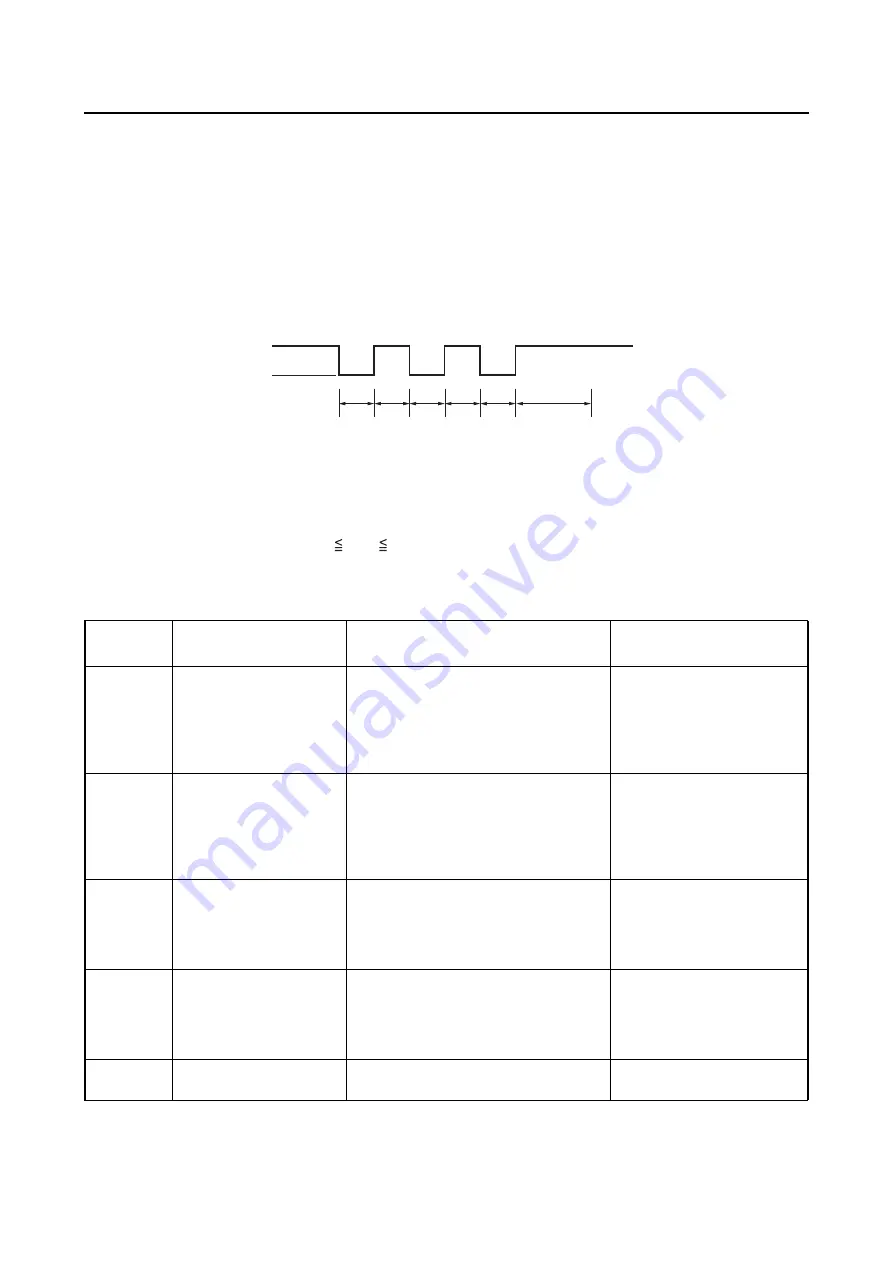
Deleting fault codes
To delete fault codes, ground the EPS self-diagnosis signal connector 3 or more times within 5 seconds
while the present or past malfunction mode is activated. The currently selected mode remains active
after the fault codes of that mode are deleted.
T1: Connector grounded - - - - 0.1
T1
1.6 seconds
T2: Fault codes deleted - - - - - Maximum 1.5 seconds required
EBS30290
SELF-DIAGNOSTIC FUNCTION TABLE (EPS SYSTEM)
a
b
c
T1
T1
T1
T1
T1
T2
a. EPS self-diagnosis signal connector
b. Disconnected
c. Grounded
Fault code
No.
Item
Symptom
Probable cause of mal-
function
11
13
15
16
EPS torque sensor
No normal signals are received from
the torque sensor.
• Open or short circuit in
wire harness.
• Malfunction in torque sen-
sor.
• Malfunction in EPS control
unit.
21
Speed sensor
No normal signals are received from
the speed sensor.
• Open or short circuit in
wire harness.
• Malfunction in speed sen-
sor.
• Malfunction in EPS control
unit.
22
Engine speed signal
No normal signals are received from
the ECU.
• Open or short circuit in
wire harness.
• Malfunction in ECU.
• Malfunction in EPS control
unit.
41
42
43
45
EPS motor
No normal signals are received from
the EPS motor.
• Open or short circuit in
wire harness.
• Malfunction in EPS motor.
• Malfunction in EPS control
unit.
52
EPS control unit
Relay contacts in the EPS control unit
are welded together.
Malfunction in EPS control
unit.
Summary of Contents for 2016 Grizzly yf700gg
Page 6: ......
Page 8: ......
Page 11: ...IDENTIFICATION 1 2 ...
Page 37: ...ENGINE SPECIFICATIONS 2 6 Air induction system Solenoid resistance 18 22 Ω ...
Page 58: ...LUBRICATION SYSTEM CHART AND DIAGRAMS 2 27 EBS30023 LUBRICATION DIAGRAMS 6 7 8 9 3 4 3 2 1 5 ...
Page 60: ...LUBRICATION SYSTEM CHART AND DIAGRAMS 2 29 1 2 3 4 5 ...
Page 62: ...COOLING SYSTEM DIAGRAMS 2 31 EBS20021 COOLING SYSTEM DIAGRAMS 1 2 3 10 9 8 6 7 5 4 ...
Page 78: ...CABLE ROUTING 2 47 Front and rear brake hoses F 3 F 3 F 3 3 I G H 4 4 B C D 2 E D 2 A 1 ...
Page 80: ...CABLE ROUTING 2 49 ...
Page 83: ......
Page 119: ...PERIODIC MAINTENANCE 3 36 A Headlight left and right B Handle mounted light b a 1 A b a 1 B ...
Page 120: ...PERIODIC MAINTENANCE 3 37 ...
Page 197: ...REAR ARMS AND REAR SHOCK ABSORBER ASSEMBLIES 4 74 7 9 8 9 7 3 5 4 5 3 6 2 10 10 1 ...
Page 198: ...REAR ARMS AND REAR SHOCK ABSORBER ASSEMBLIES 4 75 ...
Page 203: ...ENGINE INSPECTION 5 2 Top cover Refer to GENERAL CHASSIS 2 on page 4 6 ...
Page 244: ...ELECTRIC STARTER 5 43 a b b 1 2 3 ...
Page 316: ...AIR INDUCTION SYSTEM 7 9 EBS20057 AIR INDUCTION SYSTEM 3 4 1 2 3 4 1 2 ...
Page 352: ...REAR CONSTANT VELOCITY SHAFT ASSEMBLIES FINAL DRIVE ASSEMBLY AND REAR DRIVE SHAFT 8 31 ...
Page 355: ......
Page 365: ...ELECTRIC STARTING SYSTEM 9 10 ...
Page 369: ...CHARGING SYSTEM 9 14 ...
Page 417: ...FUEL PUMP SYSTEM 9 62 ...
Page 434: ...ELECTRICAL COMPONENTS 9 79 1 2 3 5 7 8 9 10 11 12 13 14 15 16 17 18 19 4 6 ...
Page 454: ...ELECTRICAL COMPONENTS 9 99 ...
Page 468: ......
Page 469: ......
Page 470: ......