


PERIODIC MAINTENANCE
3-33
c. Release the brake lever so that “a” is 0 mm (0
in), and then verify that the drive select lever
cannot be shifted to “R” (reverse) from “N”
(neutral), or to “P” (park) from “R” (reverse).
d. If the operation of the drive select lever is in-
correct, repeat steps (a) to (c).
e. Tighten the locknut.
▲▲▲
▲
▲ ▲▲▲
▲
▲ ▲▲▲
▲
▲ ▲▲▲
▲
▲ ▲▲▲
▲
▲ ▲▲▲
▲
▲▲▲
▼▼▼
▼
▼ ▼▼▼
▼
▼ ▼▼▼
▼
▼ ▼▼▼
▼
▼ ▼▼▼
▼
▼ ▼▼▼
▼
▼▼▼
Drive select lever shift rod:
a. Make sure the drive select lever and trans-
mission are in “N” (neutral).
b. Loosen both locknuts “1”.
c. Adjust the length “a” of the shift rod to 410
mm (16.1 in).
d. Tighten the locknuts.
e. Start the engine, and then check that the
drive select lever can be shifted to each shift
position and that the appropriate indicator
light comes on when the lever is in each po-
sition.
TIP
If the neutral indicator light does not come on
when the drive select lever is in the “N” (neutral)
position, stop the engine. Then, with the drive
select lever in the “N” (neutral) position and with-
out opening the throttle, start the engine and
check that the neutral indicator light comes on.
f. Adjust the shift control cable again if neces-
sary.
▲▲▲
▲
▲ ▲▲▲
▲
▲ ▲▲▲
▲
▲ ▲▲▲
▲
▲ ▲▲▲
▲
▲ ▲▲▲
▲
▲▲▲
EBS30446
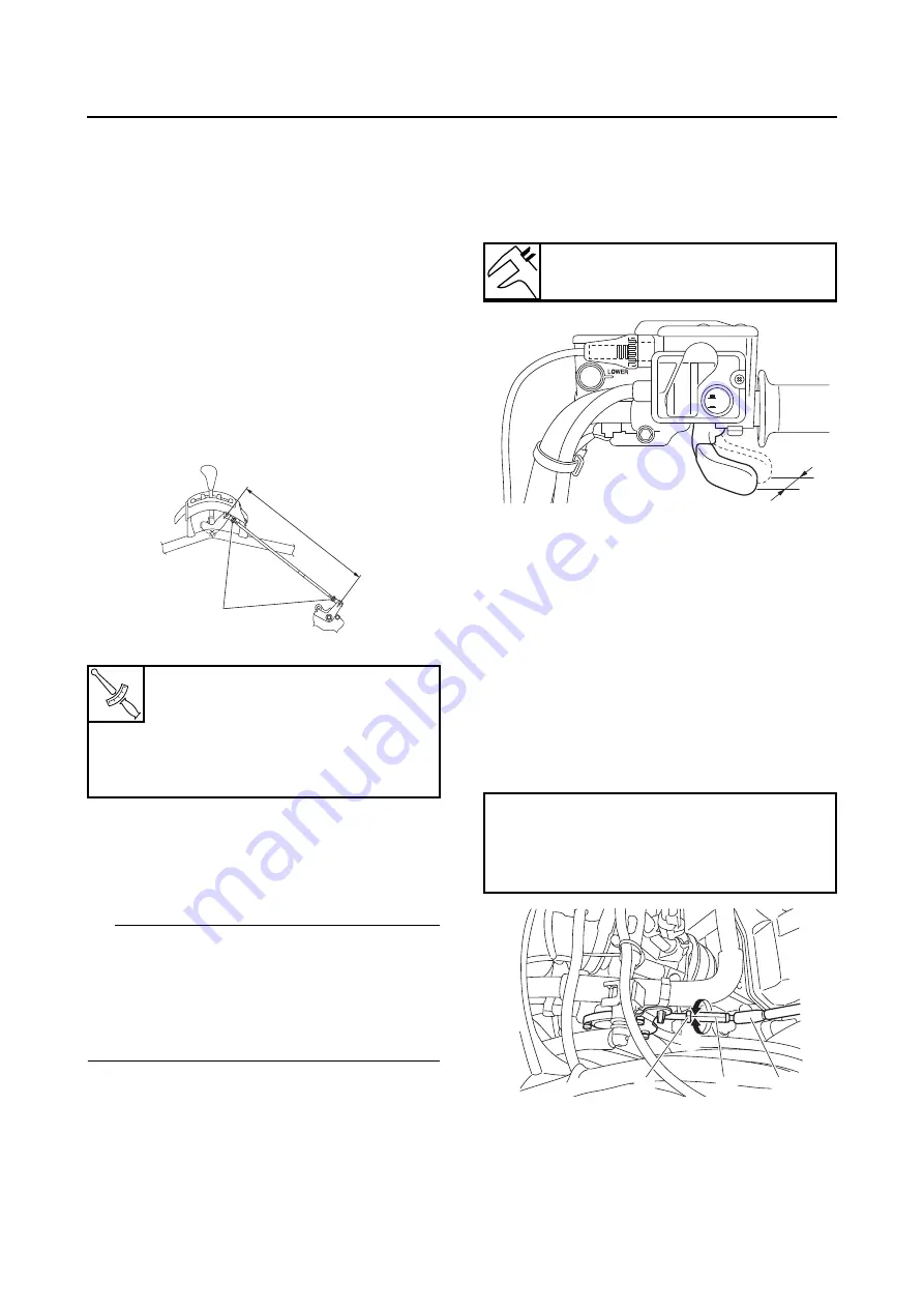
ADJUSTING THE THROTTLE LEVER FREE
PLAY
1. Check:
• Throttle lever free play “a”
Out of specification
→
Adjust.
2. Remove:
• Storage compartment
Refer to “GENERAL CHASSIS (5)” on page
4-17.
3. Adjust:
• Throttle lever free play
▼▼▼
▼
▼ ▼▼▼
▼
▼ ▼▼▼
▼
▼ ▼▼▼
▼
▼ ▼▼▼
▼
▼ ▼▼▼
▼
▼▼▼
Throttle body side
a. Slide back the rubber cover “1”.
b. Loosen the locknut “2” on the throttle body
side.
c. Turn the adjusting nut “3” in direction “a” or “b”
until the correct free play is obtained.
d. Tighten the locknut.
e. Slide the rubber cover to its original position.
T
R
.
.
Drive select lever shift rod lock-
nut (select lever unit side)
8 Nm (0.8 m·kgf, 5.8 ft·lbf)
Drive select lever shift rod lock-
nut (shift arm side)
8 Nm (0.8 m·kgf, 5.8 ft·lbf)
N
N
a
1
Throttle lever free play
3.0–5.0 mm (0.12–0.20 in)
Direction “a”
Free play is increased.
Direction “b”
Free play is decreased.
2WD
4WD
a
b
a
2
3
1
Summary of Contents for 2016 Grizzly yf700gg
Page 6: ......
Page 8: ......
Page 11: ...IDENTIFICATION 1 2 ...
Page 37: ...ENGINE SPECIFICATIONS 2 6 Air induction system Solenoid resistance 18 22 Ω ...
Page 58: ...LUBRICATION SYSTEM CHART AND DIAGRAMS 2 27 EBS30023 LUBRICATION DIAGRAMS 6 7 8 9 3 4 3 2 1 5 ...
Page 60: ...LUBRICATION SYSTEM CHART AND DIAGRAMS 2 29 1 2 3 4 5 ...
Page 62: ...COOLING SYSTEM DIAGRAMS 2 31 EBS20021 COOLING SYSTEM DIAGRAMS 1 2 3 10 9 8 6 7 5 4 ...
Page 78: ...CABLE ROUTING 2 47 Front and rear brake hoses F 3 F 3 F 3 3 I G H 4 4 B C D 2 E D 2 A 1 ...
Page 80: ...CABLE ROUTING 2 49 ...
Page 83: ......
Page 119: ...PERIODIC MAINTENANCE 3 36 A Headlight left and right B Handle mounted light b a 1 A b a 1 B ...
Page 120: ...PERIODIC MAINTENANCE 3 37 ...
Page 197: ...REAR ARMS AND REAR SHOCK ABSORBER ASSEMBLIES 4 74 7 9 8 9 7 3 5 4 5 3 6 2 10 10 1 ...
Page 198: ...REAR ARMS AND REAR SHOCK ABSORBER ASSEMBLIES 4 75 ...
Page 203: ...ENGINE INSPECTION 5 2 Top cover Refer to GENERAL CHASSIS 2 on page 4 6 ...
Page 244: ...ELECTRIC STARTER 5 43 a b b 1 2 3 ...
Page 316: ...AIR INDUCTION SYSTEM 7 9 EBS20057 AIR INDUCTION SYSTEM 3 4 1 2 3 4 1 2 ...
Page 352: ...REAR CONSTANT VELOCITY SHAFT ASSEMBLIES FINAL DRIVE ASSEMBLY AND REAR DRIVE SHAFT 8 31 ...
Page 355: ......
Page 365: ...ELECTRIC STARTING SYSTEM 9 10 ...
Page 369: ...CHARGING SYSTEM 9 14 ...
Page 417: ...FUEL PUMP SYSTEM 9 62 ...
Page 434: ...ELECTRICAL COMPONENTS 9 79 1 2 3 5 7 8 9 10 11 12 13 14 15 16 17 18 19 4 6 ...
Page 454: ...ELECTRICAL COMPONENTS 9 99 ...
Page 468: ......
Page 469: ......
Page 470: ......