6-10
FRONT BRAKE AND REAR BRAKE
HANDLING NOTE
Support the machine securely so
there is no danger of it falling over.
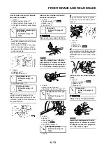
DRAINING THE BRAKE FLUID
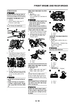
1. Remove:
• Brake master cylinder cap "1"
• Protector (rear brake)
Do not remove the diaphragm.
A. Front
B. Rear
2. Connect the transparent hose "2"
to the bleed screw "1" and place a
suitable container under its end.
A. Front
B. Rear
3. Loosen the bleed screw and drain
the brake fluid while pulling the le-
ver in or pushing down on the
pedal.
• Do not reuse the drained brake
fluid.
• Brake fluid may erode painted
surfaces or plastic parts. Always
clean up spilled fluid immediate-
ly.
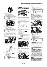
REMOVING THE BRAKE CALIPER
PISTON
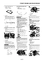
1. Remove:
• Brake caliper piston
Use compressed air and proceed
carefully.
• Cover piston with rag and use ex-
treme caution when expelling
piston from cylinder.
• Never attempt to pry out piston.
Caliper piston removal steps:
a. Insert a piece of rag into the brake
caliper to lock one brake caliper.
b. Carefully force the piston out of
the brake caliper cylinder with
compressed air.
A. Front
B. Rear
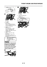
REMOVING THE BRAKE CALIPER
PISTON SEAL KIT
1. Remove:
• Brake caliper piston dust seal "1"
• Brake caliper piston seal "2"
Remove the brake caliper piston
seals and brake caliper piston dust
seals by pushing them with a finger.
Never attempt to pry out brake cal-
iper piston seals and brake caliper
piston dust seals.
Replace the brake caliper piston
seals and brake caliper piston dust
seals whenever a caliper is disas-
sembled.
A. Front
B. Rear
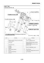
CHECKING THE BRAKE MASTER
CYLINDER
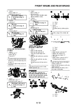
1. Inspect:
• Brake master cylinder inner sur-
face "a"
Wear/scratches
→
Replace mas-
ter cylinder assembly.
Stains
→
Clean.
Use only new brake fluid.
A. Front
B. Rear
2. Inspect:
• Diaphragm "1"
Crack/damage
→
Replace.
A. Front
B. Rear
Summary of Contents for 2010 WR450FZ
Page 4: ......
Page 12: ...1 2 LOCATION OF IMPORTANT LABELS EUROPE ...
Page 13: ...1 3 LOCATION OF IMPORTANT LABELS AUS NZ ZA ...
Page 49: ...2 18 TIGHTENING TORQUES ...
Page 51: ...2 20 LUBRICATION DIAGRAMS 1 Intake camshaft 2 Exhaust camshaft A To main axle B From oil pump ...
Page 90: ...3 31 ELECTRICAL Charging method using a variable voltage charger ...
Page 91: ...3 32 ELECTRICAL Charging method using a constant voltage charger ...
Page 125: ...5 22 CYLINDER HEAD 3 Install Bolt cylinder head 1 Bolt cylinder head 10 Nm 1 0 m kg 7 2 ft lb ...
Page 144: ...5 41 OIL PUMP 15 Oil pump drive shaft 1 16 Rotor housing 1 Order Part name Q ty Remarks ...

