5-32
CLUTCH
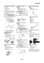
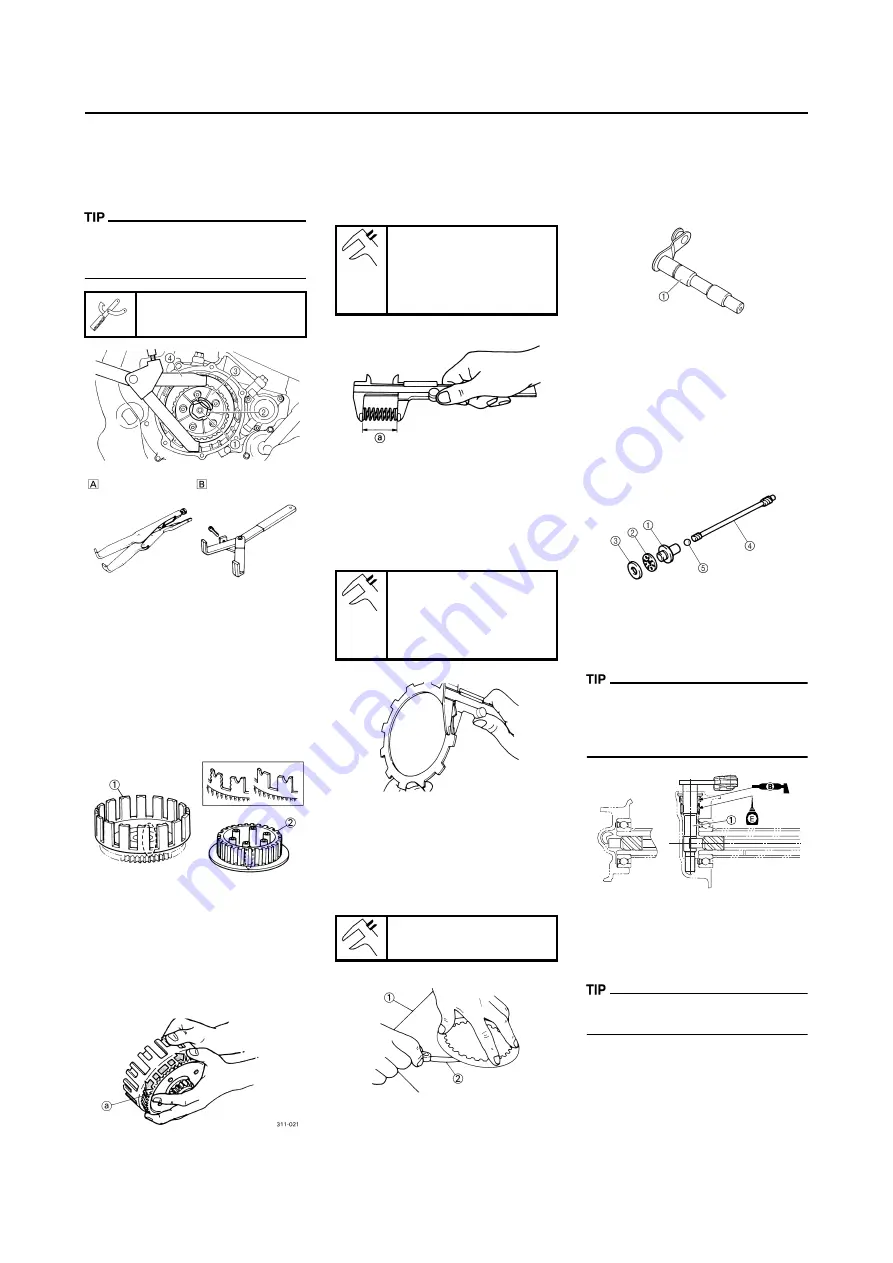
REMOVING THE CLUTCH BOSS
1. Remove:
• Nut "1"
• Lock washer "2"
• Clutch boss "3"
Straighten the lock washer tab and
use the clutch holding tool "4" to hold
the clutch boss.
A. For USA and CDN
B. Except for USA and CDN
CHECKING THE CLUTCH
HOUSING AND BOSS
1. Inspect:
• Clutch housing "1"
Cracks/wear/damage
→
Replace.
• Clutch boss "2"
Scoring/wear/damage
→
Replace.
CHECKING THE PRIMARY DRIVEN
GEAR
1. Check:
• Circumferential play
Free play exists
→
Replace.
• Gear teeth "a"
Wear/damage
→
Replace.
CHECKING THE CLUTCH
SPRINGS
1. Measure:
• Clutch spring free length "a"
Out of specification
→
Replace
springs as a set.
CHECKING THE FRICTION
PLATES
1. Measure:
• Friction plate thickness
Out of specification
→
Replace
friction plate as a set.
Measure at all four points.
CHECKING THE CLUTCH PLATES
1. Measure:
• Clutch plate warpage
Out of specification
→
Replace
clutch plate as a set.
Use a surface plate "1" and thick-
ness gauge "2".
CHECKING THE PUSH LEVER
SHAFT
1. Inspect:
• Push lever shaft "1"
Wear/damage
→
Replace.
CHECKING THE PUSH ROD
1. Inspect:
• Push rod 1 "1"
• Bearing "2"
• Washer "3"
• Push rod 2 "4"
• Ball "5"
Wear/damage/bend
→
Replace.
INSTALLING THE PUSH LEVER
SHAFT
1. Install:
• Push lever shaft "1"
• Apply the lithium soap base grease
on the oil seal lip.
• Apply the engine oil on the push le-
ver shaft.
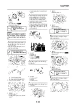
INSTALLING THE CLUTCH
1. Install:
• Primary driven gear "1"
• Thrust washer "2"
• Clutch boss "3"
Apply the engine oil on the primary
driven gear inner circumference.
Clutch holding tool:
YM-91042/90890-04086
Clutch spring free
length:
50.0 mm (1.97 in)
<Limit>: 49.0 mm (1.93
in)
Friction plate thickness:
2.92–3.08 mm (0.115–
0.121 in)
<Limit>: 2.8 mm (0.110
in)
Warp limit:
0.1 mm (0.004 in)
Summary of Contents for 2010 WR450FZ
Page 4: ......
Page 12: ...1 2 LOCATION OF IMPORTANT LABELS EUROPE ...
Page 13: ...1 3 LOCATION OF IMPORTANT LABELS AUS NZ ZA ...
Page 49: ...2 18 TIGHTENING TORQUES ...
Page 51: ...2 20 LUBRICATION DIAGRAMS 1 Intake camshaft 2 Exhaust camshaft A To main axle B From oil pump ...
Page 90: ...3 31 ELECTRICAL Charging method using a variable voltage charger ...
Page 91: ...3 32 ELECTRICAL Charging method using a constant voltage charger ...
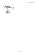
Page 125: ...5 22 CYLINDER HEAD 3 Install Bolt cylinder head 1 Bolt cylinder head 10 Nm 1 0 m kg 7 2 ft lb ...
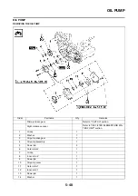
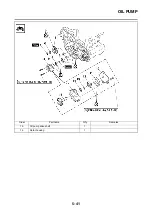
Page 144: ...5 41 OIL PUMP 15 Oil pump drive shaft 1 16 Rotor housing 1 Order Part name Q ty Remarks ...

